TIME LAPSE VCR SERVICE MANUAL CAUTION BEFORE SERVICING THE UNIT, READ THE “SAFETY PRECAUTIONS” IN THIS MANUAL. MENU REC REW F.
TABLE OF CONTENTS SECTION 1 SUMMARY • SPECIFICATIONS ......................................................1-1 • LOCATION OF CUSTOMER CONTROLS .................1-2 • CRITICAL PARTS REPLACING TIME TABLE...........1-5 • CRITICAL PARTS DESCRIPTION .............................1-5 SECTION 2 CABINET & MAIN FRAME EXPLODED VIEWS........................................................2-1 1. Cabinet and Main Frame Section ............................2-1 2. Packing & Accessory Section ...............................
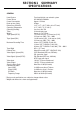
SECTION1 SUMMARY SPECIFICATIONS GENERAL Head System Power Source Power Consumption Back up time (clock) Dimensions (WxHxD) Operating Temperature Operating Humidity Timer Weight Tape Speed (NTSC) Tape Speed (PAL) Maximum Recording Time Tape Width Rewind Time Video Signal System(PAL) Video Signal System(NTSC) Video Input Video Output Signal to Noise Ratio Conventional audio Input (LINE) Output (LINE) S/N Ratio Frequency Range Four head helical scan azimuth system AC 100-240V, 50/60Hz Approx.
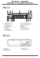
SECTION1 SUMMARY LOCATION OF CUSTOMER CONTROLS FRONT 1 2 3 4 5 6 7 8 9 POWER/TIMER BUTTON MENU BUTTON REC (RECORD) BUTTON MOVE BUTTON SEL (SELECT) BUTTON DOWN BUTTON UP BUTTON ALARM INDICATOR KEY LOCK INDICATOR 10 CASSETTE LOADING SLOT 11 CLEAR, KEY LOCK OFF, BUZZER OFF 12 CLOCK, COUNT, REMAIN 13 SHUTTLE RING 14 JOG RING 15 PAUSE/STILL BUTTON 16 PLAY/REC CHECK BUTTON 17 STOP/EJECT BUTTON REAR 1 POWER CORD 2 AUDIO IN/OUT JACK 3 VIDEO IN/OUT JACK 4 RESET BUTTON 5 12-PIN TERMINAL BLOCK 1-2
SECTION1 SUMMARY LOCATION OF CUSTOMER CONTROLS INDICATOR PANEL 1 2 3 4 5 6 TIME LAPSE VCR TIME INDICATION ALARM INDICATION SERIES INDICATION RECORD INDICATION TIMER INDICATION CASSETTE INDICATION 7 INDEX INDICATION 8 POWER FAILURE INDICATION 9 KEY LOCK INDICATION 10 REPEAT INDICATION 11 FUNCTION INDICATION 12 VCR FUNCTION INDICATION VCR FUNCTION INDICATION 1-3
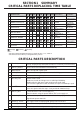
SECTION1 SUMMARY LOCATION OF CUSTOMER CONTROLS TERMINAL SIGNAL LEVELS TERMINAL SIGNAL LEVEL IN/OUT DESCRIPTION 1. ALARM IN VIH : 4 ~ 5V VIL : 0 ~ 0.6V T : above 250 msec INPUT The input signal that makes ‘Alarm Record’ work 2. ALARM OUT VIH : 4 ~ 5V VIL : 0 ~ 0.6V T : ALARM REC STATE OUTPUT Outputs whether ‘Alarm Recording’ is working 3.ALARM RESET VIH : 4 ~ 5V VIL : 0 ~ 0.6V T : above 250 msec INPUT The terminal that stops ‘Alarm Record’ in Auto mode 5. SERIES IN VIH : 4 ~ 5V VIL : 0 ~ 0.
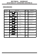
SECTION1 SUMMARY CRITICAL PARTS REPLACING TIME TABLE No. DESCRIPTION 1 1500 3000 5000 6000 7500 9000 10000 12000 Test freatures DRUM ASSY Specification RF out level -4dB and below 2 ARM ASSY CLEANER Wear status Whether extraneous matters come out 3 MOTOR CAPSTAN (D-35) W/F(WTD) 0.
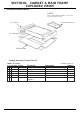
SECTION2 CABINET & MAIN FRAME EXPLODED VIEWS 1. Cabinet and Main Frame Section Cabinet & Main Frame Section Parts list MODEL : TL-AT130M S AL LOCA.NO.
SECTION2 CABINET & MAIN FRAME EXPLODED VIEWS 1-1. Cabinet and Main Frame Section Cabinet & Main Frame Section Parts list ASSEMBLY PARTS SECTION A42 6871RK5700K Ass'y Front PCB SNILN4T3526 A43 05503805 ASS'Y FRONT CAVINET NTH960 C-TYPE A44 6871R-4462A Ass'y Ant.
SECTION2 CABINET & MAIN FRAME EXPLODED VIEWS 2. Packing & Accessory Section ✒ NOTE Refer to “REPLACEMENT PARTSLIST” in order to look for the part number of each part. 801 INSTRUCTION ASS’Y 803 : PACKING 804: SHEET ROLL 802: BOX CARTON • Packing Accessory Section Parts list MODEL : TL-AT130M S AL LOCA.NO. 801 802 803 804 808 900 PART NO 3835RS0069N 3890R-C065K 3920R-E016A 3858R-S001A 534-008C 6711R1P041H RUN DATE : 2004.03.
SECTION3 ELECTRICAL ELECTRICAL ADJUSTMENT PROCEDURES 1. PG ADJUSTMENT MODE SPECIFICATION OBJECT MEASURED OBJECT ADJUSTED PLAYBACK IN SP PG : 416 ± 20 sec V.OUT JACK VR501 1. Connect CH-1 of the oscilloscope to W357 and W362, and adjust it to 1Vp-p as TRIGGER. (In case of 10:1 Probe, adjust it 50m Vp-p) 2. Connect CH-2 of the oscilloscope to V.OUT JACK and adjust it to 0.5Vp-p. (In case of 10:1 Probe, adjust it 50 Vp-p) 3. Adjust time of the oscilloscope to 0.1 msec. 4.
SECTION3 ELECTRICAL ELECTRICAL TROUBLESHOOTING GUIDE 1. Power Circuit(SMPS) (1) No 5.3 A (2) No 9V No 5.3V Is F101 normal? No 12V NO Replace F101(Use a specified Is D109 normal? fuse). YES Is BD101 normal? NO Is Q170 normal? Replace BD101. NO Replace Q170 YES NO Replace R101.
SECTION3 ELECTRICAL ELECTRICAL TROUBLESHOOTING GUIDE (4) No 5.2 A (TO AVCP, BIAS) (5) No 10V No 5.2V Is D106 normal? No 10V NO Is D109 normal? Replace D106. YES Is Q153 normal? Replace D109 YES NO Is Q170 normal?, Is there about Replace Q153. 13.5V at Q107 Base? YES YES Is there voltage (about 0V) NO NO Check/ Replace Replace Q157. at Q157 collector. D155, D156, D157/\.
SECTION3 ELECTRICAL ELECTRICAL TROUBLESHOOTING GUIDE 2. SERVO CIRCUIT (1) Video is unstable in PB mode In PB mode Does noise level on the screen change periodically? YES Does CTL pulse appear at NO IC501 Pin 76? NO Is adjusting height of CTL Readjust the height of CTL fead. head accurate? YES NO Replace IC501. Does CTL pulse move on tracking? YES Does Video Envelope wave form NO appear at IC501 pin 86? Check the Pre-Amp circuit YES Replace IC501.
SECTION3 ELECTRICAL ELECTRICAL TROUBLESHOOTING GUIDE (3) Capstan motor stops When the capstan motor stops Is it 12VA at PMC01 Pin2? NO Check Power circuit YES NO Is there 2.
SECTION3 ELECTRICAL ELECTRICAL TROUBLESHOOTING GUIDE 3. Y/C CIRCUIT (1) No Video in EE Mode No Video in EE Mode Does the Video signal appear at the NO Check the Video input Jack & IC3G1 Pin9? jack Board connection. YES Does the Video signal appear NO Check the IC3G1 Pin14 at the IC301 Pin38? and Q3G1 emitter. YES Is 5V applied to the NO Check the 5VA Line.
SECTION3 ELECTRICAL ELECTRICAL TROUBLESHOOTING GUIDE (2) When the Y(Luminance)signal doesn’t appear on the screen in PB Mode. Is 5V applied to the IC301 Pin 16, 40, 55, 58, 87? Is the I2C Bus signal applied NO Check the line of the 5.3VA Line. (Power Circuit) NO Check the System Circuit. (Refer to 2 to the IC301 Pin 23, 24? ‘SYSTEM I C BUS Trouble Shooting’) YES Does the normal RF signal NO appear at the IC301 Pin74? Is the V.H.S/W "H" about NO Check the System Circuit. (IC501 Pin 23) 3.
SECTION3 ELECTRICAL ELECTRICAL TROUBLESHOOTING GUIDE (3) When the C(Color) signal doesn't appear on the screen in PB Mode NO Is 5V applied to the IC301 Pin 16, 40, 55, 58, 87? Is the Color Rotary signal applied to Check the line of the 5.3VA Line. (Power Circuit) NO Check the Color Rotary the IC301 Pin 10? Circuit. (IC501 pin 98) YES NO Is Color Rotary "H" about Check the Color Rotary level. 1.
SECTION3 ELECTRICAL ELECTRICAL TROUBLESHOOTING GUIDE 4. AUDIO CIRCUIT (1) No sound in EE Mode (2) No sound in PB MODE No sound in EE Mode. No sound in PB Mode. YES YES No sound. No sound. YES YES NO Is 5V applied to the IC301 Pin 75? Check the line of the 5V Line. Is 5V applied to the (Power Circuit) IC301 Pin 75? NO Check the line of the 5V Line.
SECTION3 ELECTRICAL ELECTRICAL TROUBLESHOOTING GUIDE (3) No sound in REC Mode. NO sound in REC Mode. YES Sound is not recorded. YES Is Playback O.K.? NO Refer to "No sound in PB Mode,". YES Is the Audio signal applied NO Check the path of Line Audio.
SECTION3 ELECTRICAL ELECTRICAL TROUBLESHOOTING GUIDE 5. SYSTEM/KEY CIRCUIT (1) AUTO STOP Auto Stop YES Does SW waveform appear at IC501 NO pin23? Check Drum motor signal YES Does T/up reel pulse appear at IC501 Pin27? YES NO Does T/up reel pulse appear NO Is there 5.3V at RS501? at Q514 Base terminal? YES NO YES Replace T/up reel sensor of deck Replace IC501 Check DP06, LP03 Check power circuit (2) No cassette tape loading No cassette tape loading YES NO Is there REG.
SECTION3 ELECTRICAL ELECTRICAL TROUBLESHOOTING GUIDE (3) No Key display No Key display YES Is there 5.2VA at IC501 Pin79, 80, 81? NO Check power circuit YES As pressing the byttons doeseach NO Replace bad switches function work properly? 6. OSD CIRCUIT (2) No F.OSD display. (1) No OSD display. No F.OSD display. No OSD display. YES YES Is there 5.3V IC501 Pin 51? NO Check 5.3V Line of power Refer to “(5) No OSD picture” NO Does video signal appear at Replace X502.
SECTION3 ELECTRICAL BLOCK & CIRCUIT DIAGRAMS 1.
SECTION3 ELECTRICAL BLOCK & CIRCUIT DIAGRAMS 2.
SECTION3 ELECTRICAL BLOCK & CIRCUIT DIAGRAMS 3.
SECTION3 ELECTRICAL BLOCK & CIRCUIT DIAGRAMS 4.
SECTION3 ELECTRICAL BLOCK & CIRCUIT DIAGRAMS 5.
SECTION3 ELECTRICAL BLOCK & CIRCUIT DIAGRAMS 6.
SECTION3 ELECTRICAL BLOCK & CIRCUIT DIAGRAMS 3-23
SECTION3 ELECTRICAL BLOCK & CIRCUIT DIAGRAMS 7.
SECTION3 ELECTRICAL BLOCK & CIRCUIT DIAGRAMS 3-26
SECTION3 ELECTRICAL BLOCK & CIRCUIT DIAGRAMS 8.
SECTION3 ELECTRICAL BLOCK & CIRCUIT DIAGRAMS 9.
SECTION3 ELECTRICAL BLOCK & CIRCUIT DIAGRAMS 10.
SECTION3 ELECTRICAL PRINTED CIRCUIT DIAGRAMS 1. MAIN P.C.
SECTION3 ELECTRICAL PRINTED CIRCUIT DIAGRAMS 2. KEY 1 P.C.BOARD 3. KEY 2 P.C.BOARD PRINTED CIRCUIT BOARD DIAGRAMS 4. JACK P.C.
SECTION 4 MECHANISM CONTENTS DECK MECHANISM PARTS LOCATIONS • Top View......................................................4-1 • Bottom View ...............................................4-1 DECK MECHANISM DISASSEMBLY 1. Drum Assembly .........................................4-2 2. Plate Top ...................................................4-4 3. Holder Assembly CST ...............................4-4 4. Opener Door .............................................4-4 5. Bracket Assembly L/D Motor..........
DECK MECHANISM PARTS LOCATIONS • Top View Procedure Starting No.
DECK MECHANISM DISASSEMBLY Stator (S2) (S2) (S3) Drum Motor (S3) Rotor Drum Sub Assembly (Fig. A-1-1) (A) Drum FPC Carbon Brush (S1) (S1) (S1) H2 H1 Holder FPC Fig. A-1 (Fig. B-1) 1. Drum Assembly (Fig. A-1-1) 1) Unplug the Drum FPC Connector. 2) Remove three Screws(S1) on bottom side and separate the Drum assembly. 3) Unhook (H1), (H2) and separate the Holder FPC and Cap FPC. Cap FPC 1-1. Drum Motor 1) Remove two Screws(S2) and disassemble the Stator of the Drum Motor.
DECK MECHANISM DISASSEMBLY Plate Top (Fig. A-2-1) (C) (B') (B) Holder Assembly CST (Fig. A-2-2) (E) Arm Assembly F/L (Fig. A-2-6) Lever Assembly S/W (Fig. A-2-7) (H8) (C1) Bracket Assembly L/D Motor Spring Lever S/W (Fig. A-2-4) (C') (D) (E') Opener Door (Fig. A-2-3) (H6) Chassis (A) Gear Assembly Rack F/L (Fig. A-2-5) Fig.
DECK MECHANISM DISASSEMBLY 2. Plate Top (Fig. A-2-1) 1) Pull the (B) portion of the Plate Top back in direction of arrow and separate the right side of it. 2) pull the (B’) portion of the Plate Top back in direction of arrow and separate the left side of it. (Used tools : (-) type driver, anything tool with sharp point or flat point.) 2) Unhook three Hooks(H3, H4, H5) on bottom side of the Chassis, lift up the Bracket Assembly L/M and disassemble the Bracket Assembly L/D Motor.
DECK MECHANISM DISASSEMBLY Arm Assembly Cleaner (Fig. A-3-1) (A) (S4) Base Assembly A/C Head (A) (Fig. A-3-3) Head F/E (Fig. A-3-2) Chassis Fig. A-3 9. Arm Assembly Cleaner (Fig. A-3-1) 11. Base Assembly A/C Head (Fig. A-3-3) 1) Breakaway the (A) portion as Fig. A-3-1 from the embossing of the Chassis, turn the Arm assembly Cleaner to clockwise direction and lift it up. 1) Remove the Screw(S4) and lift the Base Assembly A/C Head up. 10. Head F/E (Fig.
DECK MECHANISM DISASSEMBLY Arm Assembly Tension (Fig. A-4-3) (H11) Spring TB Brake Assembly T (Fig. A-4-1) Spring Tension Reel S Reel T (Fig. A-4-4) (Fig. A-4-4) Spring RS Brake Assembly RS (Fig. A-4-2) (H12) (H9) (H10) Base Tension Chassis Fig. A-4 12. Brake Assembly T (Fig. A-4-1) NOTE 1) Unhook the Spring TB from the Hook(H9) of the Chassis. 2) Lift the Brake Assembly T up. Difference for Springs Spring TB Spring RS Color (Black) Spring Tension 13. Brake Assembly RS (Fig.
DECK MECHANISM DISASSEMBLY Opener Lid (Fig. A-5-2) (B) (B) Arm Assembly Pinch (Fig. A-5-3) (C) Base Assembly P4 Lever T/up (Fig. A-5-1) (Fig. A-5-4) (H13) (C) Arm T/up (H13) (Fig. A-5-5) (A) Chassis Fig. A-5 16. Base Assembly P4 (Fig. A-5-1) NOTE 1) Breakaway the (A) portion of the Base Assembly P4 from the embossing of the Chassis. 2) Turn the Base Assembly P4 to counterclockwise direction and lift it up.
DECK MECHANISM DISASSEMBLY Belt Capstan (Fig. A-6-1) Motor Capstan (Fig. A-6-2) Washer(W1) Clutch Assembly D35 (Fig. A-6-4) (L1) (L1) Brake Assembly Capstan (Fig. A-6-5) Lever F/R (Fig. A-6-3) (L2) Chassis (S5) Fig. A-6 22. Clutch Assembly D35 (Fig. A-6-4) 20. Belt Capstan (Fig. A-6-1)/ Motor Capstan (Fig. A-6-2) 1) Remove the Belt Capstan. 2) Remove the three Screws(S5) on bottom Chassis and lift the Motor Capstan up. 21. Lever F/R (Fig. A-6-3) 1) Unlock the Locking Tab(L1) as Fig.
DECK MECHANISM DISASSEMBLY (H14) Gear Cam Hole(B) Gear Drive Hole(A) Gear Cam (Fig. A-7-2) Gear Sector Washer (W2) (Fig. A-7-3) Plate Slider Gear Drive (Fig. A-7-4) (Fig. A-7-1) (A) Lever Tension (Fig. A-7-5) Lever spring (L3) (Fig. A-7-6) Gear Drive Hole(C) Base Loading (H15) (H16) Chassis Fig. A-7 24. Gear Drive (Fig. A-7-1)/ Gear Cam (Fig. A-7-2) 26. Plate Slider (Fig. A-7-4) 1) Just lift the Plate Slider up. 1) Remove the Washer(W2) and lift the Gear Drive up.
DECK MECHANISM DISASSEMBLY Gear Assembly P2 Hole Gear Assembly P3 Hole Gear Assembly P3 (Fig. A-8-2) Lever Spring Boss Gear Sector Hole(A) Gear Assembly P2 Plate Slider Hole(B) (Fig. A-8-1) (B) (A) Chassis Base Assembly P3 (Fig. A-8-4) Base Assembly P2 Fig. A-8 (Fig. A-8-3) 29. Gear Assembly P2 (Fig. A-8-1)/ Gear Assembly P3 (Fig. A-8-2) 30. Base Assembly P2 (Fig. A-8-3)/ Base Assembly P3 (Fig. A-8-4) 1) Just lift the Gear Assembly P2 up. 2) Just lift the Gear Assembly P3 up.
DECK MECHANISM DISASSEMBLY Base Tension (S7) Base Loading (Fig. A-9-2) Arm Assembly Idler (Fig. A-9-1) (A) (B) (Fig. A-9-3) (C) (D) Chassis Fig. A-9 31. Base Loading (Fig. A-9-1) 33. Arm Assembly Idler (Fig. A-9-3) 1) Remove the Screw(S7). 2) Lift the Base Loading up. 1) Make narrower the two parts, (B) and (C), as Fig. A-9-3. 2) Lift the Arm assembly Idler up. 32. Base Tension (Fig. A-9-2) NOTE 1) Breakaway the (A) portion of the Base Tension from the embossing of the Chassis.
DECK MECHANISM ADJUSTMENT • Tools and Fixfures for Service SR K 1. Cassette Torque Meter 1. SRK-VHT-303(Not SVC part) 1. Parts No: D00-D006 -V HT -S 2. Alignment Tape Parts No NTSC: DTN-001 PAL:DTN-0002 3. Torque Gauge 3. 600g.Cm ATG 3. Parts No:D00-D002 5. Post Height Adjusting Driver Parts No:DTL-0005 6. + Type Driver (ø 5) 300 250 200 150 0 50 SR VID K CAS EO S TOR ETTE Q MET UE VHT ER -303 -T K- V HT0 SR 50 100 150 200 300 250 4.
DECK MECHANISM ADJUSTMENT 1. Mechanism Alignment Position Check Purpose:To determine if the Mechanism is in the correct position, when a Tape is ejected. Test Equipment/ Fixture Test Conditions (Mechanism Condition) • Blank tape • Eject Mode (with Cassette ejected) 1) Turn the Power S/W on and eject the Cassette by pressing the Eject Button. 2) Remove the Top Cover and Plate Assembly Top, visually check if the Gear Cam Hole is aligned with the Chassis Hole as below Fig. C-2.
DECK MECHANISM ADJUSTMENT cassette without tape. Cover the holes of the End Sensors at the both sides of the Chassis to prevent a light leak. Then the Deck Mechanism drives to the Stop Mode. In this case, the Deck Mechanism can accept inputs of each mode, however the Rewind and Review operation can not be performed for more than a few seconds because the Take-up Reel Table is in the Stop State and can not be detected the Reel Pulses. 2.
DECK MECHANISM ADJUSTMENT 4.Guide Roller Height Adjustment Purpose: To regulate the height of the tape so that the bottom of the tape runs along the tape guide line on the Lower Drum. 4-1. Preliminary Adjustment Test Equipment/ Fixture • Post Height Adjusting Driver Test Conditions (Mechanism Condition) • Play or Review Mode Adjustment Procedure Adjustment Point • Guide Roller Height Adjustment screws on the Supply and Take-Up Guide Rollers.
DECK MECHANISM ADJUSTMENT 5. Audio/Control (A/C) Head Adjustment Purpose: To insure that the tape passes accurately over the Audio and Control Tracks in exact alignment of the both Record and Playback Modes. 5-1. Preliminary Adjustment (Height and Tilt Adjustment) Perform the Preliminary Adjustment, when there is no Audio Output Signal with the Alignment Tape.
DECK MECHANISM ADJUSTMENT (2) If folding or curling is observed at the top of it then slowly turn the Tilt Adjustment Screw(C) in the counterclockwise direction. 5-2. Confirm that the tape passes smoothly between the Take-up Guide and Pinch Roller(using a mirror or the naked eye). 1) After completing Step 5-1.(Preliminary Adjustment), check that the tape passes around the Take-up Guide and Pinch Roller without folding or curling at the top or bottom.
DECK MECHANISM ADJUSTMENT 7. Adjustment after Replacing Drum Assembly (Video Heads) Purpose: To correct for shift in the Roller Guide and X value after replacing the Drum.
MAINTENANCE/INSPECTION PROCEDURE 1. Check before starting repairs The following faults can be remedied by cleaning and oiling. Check the needed lubrication and the conditions of cleanliness in the unit. Check with the customer to find out how often the unit is used, and then determine that the unit is ready for inspection and maintenance. Check the following parts.
MAINTENANCE/INSPECTION PROCEDURE 2. Required Maintenance The recording density of a VCR(VCP) is much higher than that of an audio tape recorder. VCR(VCP) components must be very precise, at tolerances of 1/1000mm, to ensure compatibility with the other VCRs. If any of these components are worn or dirty, the symptoms will be the same as if the part is defective. To ensure a good picture, periodic inspection and maintenance, including replacement of worn out parts and lubrication, is necessary.
MAINTENANCE/INSPECTION PROCEDURE 5-2) Greasing (1) Greasing guidelines Apply grease, with a cleaning patch. Do not use excessive grease. It may come into contact with the tape transport or drive system. Wipe excessive grease and clean with cleaning patch wetted in Isopropyl Alcohol. (2) Periodic greasing Grease specified locations every 5,000 hours.
MAINTENANCE/INSPECTION PROCEDURE Lever, F/R, Base, Tension GEAR AY, P2 & P3 Lever, F/R Boss Base, Tension Clutch (G-754.
MECHANISM TROUBLESHOOTING GUIDE 1.Deck Mechanism A. Auto REW doesn't work. YES Is the output of END sensor of supply side "H"? “H”: more than 3.5V “L”: less than 0.7V~1V YES NO Is the Vcc. voltage of End sensor 5V? NO Check the syscon power. YES Replace the End sensor. Is the voltage across IR LED between 0.8~1.5V? NO Replace the IR LED. YES Check the syscon circuit. B. No F/R modes. YES Is the present mode F/R Mode? NO Is the mode SW assembled correctly? (refer to page 4-13.
MECHANISM TROUBLESHOOTING GUIDE C. AUTO STOP. (PLAY/CUE/REV) Check alignment positions (page 4-13). In Play/Cue/Rev, Is the Pinch Roller in contact with the Capstan Shaft? NO Is the output of DFG, DPG OK? YES Are there T/up and Supply Reel pulses. Replace the Drum Motor. NO YES NO Check the Servo, Syscon. YES Check the Syscon, µ-COM. Replace the Reel Sensor. D. Cassette doesn’t load. Insert the cassette. YES Does the Lever Assembly S/W work normally? NO Check Lever Assembly S/W.
MECHANISM TROUBLESHOOTING GUIDE E. In PB mode Tape Presence not sensed. Is the Pinch Roller attached to the Capstan Motor Shaft? NO Check Alignment positions (page 4-13). YES NO Does the T/Up Reel turn? NO Is the Belt ok? YES Replace the Belt. YES Check the Clutch and Idler Assembly.
MECHANISM TROUBLESHOOTING GUIDE 2. Front Loading Mechanism A. Cassette cannot be inserted. Does the Lever Assembly Switch work? NO Is the Lever Assembly Switch Spring damaged or omitted? YES YES Does the CST IN Switch work normally? Is the Vcc of Main P.C.Board 5V? NO Replace or add the Lever Assembly Switch Spring. NO Replace the CST IN Switch. YES Check the syscon circuit. NO YES Is the voltage between cassette switch and GND on Main P.C.Board 5V?? Check the power circuit.
MECHANISM TROUBLESHOOTING GUIDE C. Cassette does not load. Does the cassette insert? YES Does the Opener Lid work? YES NO Does the Gear Assembly Rack F/L work? YES Replace the Opener Lid. NO Replace the Gear Rack F/L. Does the Opener Door work? YES NO Check the opener Door assembled correctly. Does the Arm Assembly F/L work? YES NO Does the L/D Motor work? YES Replace the Arm Assembly F/L. NO Does the Holder Assembly Cassette move the Arm Assembly F/L? YES Check the power of L/D Motor.
EXPLODED VIEWS 1.
EXPLODED VIEWS 2.
EXPLODED VIEWS 3.
SECTION 5. REPLACEMENT PARTS LIST NOTE: Warning Parts that are shaded are critical With respect to risk of fire or electrical shock. MODEL : NTH960N NSP : Not Service Part MECHANICAL SECTION S AL LOCA.NO PART NO.
MODEL : NTH960 S AL RUN DATE : 2004.05.01 LOCA.NO 079 100 102 103 105 106 107 109 110 112 113 114 115 116 117 116 117 PART NO.
MODEL : NTH960 Electrecal section S AL LOCA.NO. RUN DATE : 2004.05.
MODEL : NTH960 S AL LOCA.NO. C332 C333 C334 C336 C337 C338 C339 C340 C341 C343 C344 C345 C346 C348 C349 C354 C355 C358 C360 C368 C369 C375 C377 C380 C381 C384 C386 C3B1 C3G1 C3G2 C3G3 C3G4 C3G5 C3G6 C3G7 C3G8 C3G9 C401 C402 C403 C405 C406 C410 C412 C413 C414 C415 C416 C417 C418 C419 C420 C421 C424 C431 C466 C480 C490 C501 C502 RUN DATE : 2004.05.
MODEL : NTH960 S AL LOCA.NO. C503 C505 C507 C509 C510 C514 C515 C516 C517 C520 C521 C522 C525 C526 C528 C529 C530 C534 C535 C540 C541 C542 C543 C544 C545 C546 C551 C552 C554 C555 C557 C561 C567 C570 C571 C573 C574 C576 C581 C582 C583 C584 C5F1 C5F2 C6F3 C6F4 C6F5 C6F8 C5K0 C5K1 C5K2 C6R1 C601 C602 C603 C604 C605 C901 C902 C903 C904 RUN DATE : 2004.05.
MODEL : NTH960 S AL LOCA.NO. C906 C907 C908 C909 C910 C911 C917 C918 C919 C921 C922 C923 C924 RUN DATE : 2004.05.
MODEL : NTH960 S AL LOCA.NO. D903 D904 D905 RUN DATE : 2004.05.
MODEL : NTH960 S AL LOCA.NO. R121 R122 R152 R156 R157 R161 R162 R166 R167 R168 R170 R171 R172 R173 R174 R175 R177 R302 R303 R304 R305 R306 R307 R308 R309 R310 R311 R312 R313 R316 R317 R318 R319 R320 R321 R322 R326 R335 R338 R340 R341 R349 R380 R381 R384 R385 R386 R387 R388 R389 R390 R391 R392 R393 R3B1 R3G1 R3G2 R3G3 R3G4 R3G5 RUN DATE : 2004.05.
S AL LOCA.NO.
MODEL : NTH960 S AL LOCA.NO. R553 R554 R555 R556 R557 R558 R559 R560 R563 R564 R567 R569 R570 R571 R572 R573 R574 R575 R576 R577 R578 R579 R580 R581 R582 R583 R585 R589 R590 R591 R592 R593 R595 R596 R597 R598 R5B1 R5B3 R5B4 R5C5 R5C6 R5C7 R5F0 R5F1 R5F2 R5F3 R6F4 R6F5 R6F6 R6F7 R5K0 R5K1 R5K2 R6R1 R603 R604 R605 R606 R607 R608 R609 RUN DATE : 2004.05.
MODEL : NTH960 S AL LOCA.NO. R610 R611 R612 R613 R614 R615 R616 R617 R618 R621 R622 R623 R624 R625 R626 R627 R628 R629 R630 R634 R635 R636 R637 R638 R904 R905 R906 R907 R908 R909 R910 R911 R912 R914 R915 R916 R917 R918 R919 R920 R921 R922 R923 R924 R925 R926 R927 R928 R929 R930 R931 R932 R933 R934 R935 R936 R937 R938 R939 R940 RUN DATE : 2004.05.
S AL LOCA.NO.
MODEL : NTH960 S AL LOCA.NO. Q501 Q502 Q503 Q504 Q506 Q512 Q513 Q514 Q515 Q521 Q901 Q902 Q903 Q904 Q905 Q906 Q907 Q908 Q909 Q910 Q911 Q912 Q913 Q914 RUN DATE : 2004.05.