INSTALLATION MANUAL Universal flat-panel mount R LISTED E176225 3130 E. Miraloma Ave. Anaheim, CA 92806 Phone: 800 368-9700 Fax: 800 832-4888 www.mounts.
Contents - Assembly drawing Fine tune tilt adjustments Flat panel list Parts list Checking thread depth Finding the center of the flat panel Positioning the mounting brackets Securing the mounting brackets Finding the wood stud behind the wall structure Marking the bottom plate mounting points - Securing the bottom wall plate - Securing the top plate - Securing the flat panel to the wall mount - Lateral shift adjustment The wall structure should be capable of supporting a max weight of 160 Lbs.
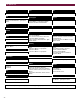
Assembly drawing Dimensions are in Inches and (mm) 28.000 (171.2) 16.000 (406.4) 1.245 (31.75) A CL B H 5.000 (127) 19.000 (482.6) 12.000 (304.8) 10.500 (266.7) CL 21.000 (533.4) 5.000 (127) C G 16.000 (406.4) D 16.000 (406.4) 16.000 (406.4) F 24.290 (616.97) E Description 2.331 (59.21) A. Wall plates G B. Mounting brackets C. Griplate™ H D. Mounting hardware E. M6 x 30 (mm) Phillip screws 1 F. Wood stud G. 5/16” x 3” Lag screws and flat washers H.
Flat panel list Acer Eizo Idex PDP7859: M6 x 20 5420T: M8 x 30 PDM4260: M4 x 16 Electrograph Ikegami DTS42W: M8 x 30 – ¼” nylon spacers (large) DTS4230: M8 x 30 – ½” nylon spacers - sleeves DTS42DD, DTS42GBDD, DTS42GB: M6 x 20 PTM4202: M5 x 20 Faroudja Integra FPP42HD10, FPP50HD10: M4 X 16 PLA50V1: M4 X 16 Akai CTA42AR7A, PDP4247, PDP4290, PDP4294, PDP5090, HPT500AN: M8 x 25 – ½” nylon spacers sleeves Akira EPM420, SV4201: M5 x 16 Albatron PWV46AC: M6 x 20 Barco Cineversum 50: M8 x 20 BenQ
Mitsubishi Princeton Graphics Tatung PD5010HD, PD5030: M4 x 16 AR3.4FTW,AR4.
Parts list NOTE: This wall mount is shipped with all proper installation hardware and components. Make sure that none of these parts are missing before beginning installation. If there are parts missing stop the installation and contact Premier Mounts.
Parts list (con’t) Nylon spacers and flat washers actual size NOTE: The nylon spacers may be staked to achieve proper spacing.
Checking the thread depth on your flat panel 1. 2. Insert the thread depth indicator (supplied) through the thread inserts found on the back of the flat panel to make sure the inserts measure the same full depth and mark it. (see figure 1) Locate the correct diameter screw for the thread insert. Compare your marking to the screws (supplied). If your selected screw is longer than the marking on the thread depth indicator DO NOT USE this screw. The screw length must not bypass the marking.
Parts list (con’t) All of these parts are used to install the mounting bracket. Make sure that none of these parts are missing before beginning installation. If there are parts missing stop the installation and contact Premier Mounts.
Finding center of the flat panel display WARNING : Proper installation procedure by qualified personnel as outlined in the installation instructions must be adhered to. Failure to do so could result in serious personal injury and possible damage to the flat panel. WARNING! INVERT THE FLAT PANEL PLACE IT ON A SOFT, FLAT SUFRACE TO PREVENT DAMAGE TO THE FLAT PANEL. USE A BLANKET, FOAM, ETC. FAILURE TO DO SO WILL RESULT IN DAMAGING THE FLAT PANEL.
Positioning the mounting brackets Nylon spacers if Applicable (see chart) on page 4 and 5 CAUTION: Check the chart on page 4 and 5 to see if your flat panel needs nylon spacers. The nylon spacers provided, must be used. Failure to do so will result in damaging the flat panel. Install the nylon spacers to the mounting points on the flat panel see figure 3. NOTE: See chart (if the nylon spacers apply to your flat panel).
Match the center of viewing guide with the center line you marked in step 1. See figure 5. CL Bottom of flat panel Align the mounting brackets Mounting bracket The mounting brackets are designed with a center of viewing guide on the side of them. See figure 6.
Securing the mounting brackets The Griplates™ have M4, M5 M6 and M8 hole patterns to fit the hardware that your flat panel requires. DIMPLES M8 EXAMPLE: If your plasma uses M8 x 20 Phillip screws. Use the M8 mounting points. See figure 7 M6 Pre install two (2) M6 x 30 (mm) Phillip pan screws to the bottom of the left and right hand side mounting brackets. Once the mounting brackets are aligned secure the Griplate™ to the flat panel.
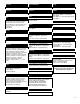
Finding the wood studs behind the wall structure Using a (commercially available) wood stud finder, locate the 16" or 24" stud centers behind the wall. Once found, make a pencil marking on the center of the wood studs. See figure 9. Wood stud finder (commercially available) Mark the wall and the center of the wood studs. NOTE: The wall plates have (3) 16" and (1) 24" mounting slot positions.
Marking the bottom plate mounting points Place the upper portion of the bottom wall plate to the reference line and mark the four (4) lag bolt mounting points through the wall plate slots on the wall. Level the wall plate with the reference arrow pointing up to the ceiling. See figure 11. Wall Wall plate plate 16" Mounting slots Wood Wood studs studs Drill gun Level Pilot holes Drill four (4) ¼" pilot holes to the marked wall. See figure 12.
Securing the bottom wall plate Level Level and secure the plate to the wall with the reference arrow facing up to the ceiling. Secure the plate using the four (4) 5/16" lag bolts and flat washers (supplied). See figure 13. CAUTION: Do not over tighten the lag bolts. Wall plate (4) 5/16" x 3" lag bolts and (4) flat washers (supplied) Marked wall When the bottom wall plate is properly installed to the wall. Lay the carton template on top of the wall plate.
Securing the top plate Drill four (4) ¼" pilot holes to the marked wall. See figure 15.
Level and secure the plate to the wall with the reference arrow facing up to the ceiling. Secure the plate using the four (4) 5/16" lag bolts and flat washers (supplied). See figure 16 CAUTION: Do not over tighten the lag bolts. NOTE: CHECK THE MOUNT FOR PROPER TIGHTNESS AND SECURITY.
Securing the flat panel to the wall mount WARNING: AT LEAST (2) QUALIFIED PERSONNEL ARE STRONGLY RECOMMENDED FOR INSTALLATION OF THIS PRODUCT. FAILURE TO DO SO COULD RESULT IN SERIOUS INJURY AND POSSIBLE DAMAGE TO THE FLAT PANEL. Raise the flat panel with the LEFT and RIGHT mounting brackets secured to the flat panel and insert the top and bottom hooks from each bracket to the rods from the wall plates. See figure 17.
Make any lateral shift adjustment and lock it by tightening the two (2) M6 x 30 (mm) Phillips screws found on the bottom of the mounting brackets. CAUTION: Do not over tighten the M6 screws to the rods.
Lateral shift adjustment Tilt the flat panel and secure the two (2) M6 x 12 (mm) safety knobs to each of the mounting brackets. See figure 19. M6 x 12 Safety knobs NOTE: To remove the display from the wall simply extend the display to its maximum tilt range, remove the two 6 (mm) safety knurl knobs push the flat panel back to it’s flat position loosen or remove the two (2) M6 x 30 lateral shift screws and lift the unit of the wall.
www.mounts.com NORTH AMERICA EUROPE ASIA 3130 East Miraloma Avenue Anaheim, CA 92806 USA USA and Canada – Phone: 800-368-9700 Fax: 800-832-4888 Swallow House, Shilton Industrial Estate, Shilton, Coventry, England CV79JY Phone: +44 (0) 2476 614700 Fax: +44 (0) 2476 614710 Yabara 1916-15, Misato-machi, Gunma-gun Gunma-ken 370-3107, Japan Phone: 81.27.371.6998 Fax: 81.27.371.6308 Other Locations – Phone: 001.714.632.7100; Fax: 001.714.632.