VACUUM CLEANER SERVICE MANUAL CAUTION BEFORE SERVICING THE UNIT, READ THE “SAFETY PRECAUTIONS” IN THIS MANUAL.
CONTENTS SAFETY PRECAUTIONS ......................................................................................................................... 3 CAUTIONS................................................................................................................................................ 3 DESCRIPTION.......................................................................................................................................... 4 SPECIFICATIONS.......................................
SAFETY PRECAUTIONS BEFORE OPERATING THIS VACUUM CLEANER, READ THIS SERVICE MANUAL THOROUGHLY, AND OBSERVE EACH POINT CAREFULLY. 1. Motor filter(Air Cleaner) 3. Avoid suction such materials as : 1) This filter is reusable. 2) Never use the vacuum cleaner without filter. It may damage the motor. 1) Liquid or wet dust : Clogs the ventilation holes, reduces the suction power significantly and harms the motor. 3) When the light of body is on, wash the motor filter with water and brush.
DESCRIPTION Cord Reel Button Flexible Hose ASS'Y Telesscopic Pipe ASS'Y Dust Tank Power Cord Filter Cover Nozzle ASS'Y CANISTER ATTACHMENTS DUSTING BRUSH & CREVICE TOOL UPHOLSTERY NOZZLE BRUSH ASS'Y SPECIFICATIONS • MODEL : REFER TO THE COVER PAGE • POWER SOURCE : ON RATING PLATE • POWER CONSUMPTION : ON RATING PLATE • POWER CONTROL : - MAIN : SLIDE CONTROL (F/HOSE) (V-C7050HT) MICOM CONTROL (F/HOSE) (V-C7070CT) PUSH ON/OFF(BODY) (V-C7050NT) • CORD LENGTH : 7m • HOSE LENGTH : 1.
DISASSEMBLY NOTE: Before attempting to service or adjust any part of the vacuum cleaner, disconnect the electrical power supply cord from the wall outlet. • Almost all the parts of this vacuum cleaner can be disassembled with a screw driver and each connecting component easily fits each other. Disassemble one by one referring to the exploded view. • If possible, don’t disassemble except for the necessary parts. It is not necessary to disassemble the parts that are not detailed in the exploded view. 1.
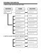
TROUBLE SHOOTING 1. SWITCH ON BUT MOTOR DOES NOT TURN CHECKING CHECK THE POWER SOURCE CAUSE SOLUTION The fuse is melt down in the coverknife switch. Exchange the fuse. Poor plug insertion Insert again. Power cord cut Repair or exchange. Interior lead wire cut Exchange the lead wire. Motor(stator, armature) coil cut or damaged. Exchange the motor. Poor contact carbon brush defaced. Exchange or repair the motor. Poor switch contact point Exchange the switch. 2.
3. SWITCH OFF BUT MOTOR TURNS Poor connection Repair. Poor switch Exchange the switch. Carbon brush defaced Exchange the carbon brush or the motor. Motor armature cut Exchange the motor. Foreign matters attached to the impeller Remove the foreign matters. Low voltage Inquire to the power utility company. Hose and extension wands are clogged with foreign matters. Remove the foreign matters in the hose or extension wands.
5. VIBRATION NOISES Loose parts Secure firmly. Unbalanced motor assembly Exchange or repair the motor. Foreign matters are attached to the impeller. Remove the foreign matters. Poor carbon brush rectification Exchange the motor. Armature is cut or foreign matters attached. Exchange the motor Remove foreign matters. 6. RADIO, TV RECEPTION DISTURBANCE Poor cord, lead wire Exchange cord, lead wire. Poor rectification of carbon brush Exchange the motor.
BLOCK DIAGRAM (V-C7050NT) POWER S/W BR BR PRESSURE S/W CORD REEL ASS'Y RD T/P PLUG RD GY MAIN PWB ASM GY BL BL MOTOR BK GY LED PWB ASM SCHEMATIC DIAGRAM (V-C7050NT) POWER S/W BR BR RD PRESSURE S/W T/P RD GY MAIN PWB ASM GY BL M BL BK GY LED PWB ASM CIRCUIT DIAGRAM (V-C7050NT) POWER S/W M R6 10,1/2W D1 1N4007 C5 0.1µF 250V C1 0.47µF 250V OPTO-TRIAC R11 470 ZD1 5.
BLOCK DIAGRAM SLIDE VOLUME (V-C7050HT) LED PWB ASM POWER S/W BK BR GY BR RD T/P RD HOSE MAIN PWB ASM SUB PWB ASM PRESSURE S/W BL BL GY GY SCHEMATIC DIAGRAM (V-C7050HT) LED PWB ASM POWER S/W BR BR SLIDE VOLUME T/P SUB PWB ASM GY PRESSURE S/W GY MAIN PWB ASM M CIRCUIT DIAGRAM (V-C7050HT) MOTOR M D6 1N4002 R8 1K R11 390 R9 100 IC1 IC2 R16 1.5K POWER S/W T/P TRANS BD1 C1 0.47uF /AC250 R12 5.
BLOCK DIAGRAM (V-C7070CT) DISPLAY PWB ASM RD DUST SENSOR PWB ASM HOSE PWB ASM RD MAIN PWB ASM SUB PWB ASM DUST SESM PWB ASM BL BL PRESSURE S/W 11 T/P
A 2.2K 4.3K 1.2K R22 R23 R24 B 11K R21 C S/W4 S/W2 S/W3 S/W1 D E R37 1 F G 12 Q17 KRC107M R36 10 CN8 CN6 Q16 KRC107M R31 10 R13 10 R32 10 R14 1.5K ST-7L Q11 KRC107M Q6 KRC107M EL-7L 2 1 Q15 KRC107M R15 1.0K CN7 C20 0.1uF Q12 KRC107M R33 10 Q5 KRC107M CN5 R24 10K R34 10 4 5 6 1 29 28 24 25 26 Q14 KRC107M 27 C12 0.01uF 25V 10 R23 10K 11 C10 0.1uF Q4 KRC107M Q13 KRC107M R13 2.
EXPLODED VIEW 135506 750063 139202 249701 140561 146811 239402 135507 152313 252301 333002 149741 333003 139204 748382 146871 236601 149308 145103 235504 252311 130401 146611 148201 235505 144411 13
135510 135510 135509 268712 135509 V-C7050NT/HT V-C7070CT/CP 335503 268712 150061 136501 250201 168711 249701 V-C7050NT V-C7050NT 168711 235501 168711 140261 349701 V-C7070CT/CP 249011 268712 166012 268711 135508 168711 452002 V-C7050NT 468011 435506 440361 435506 440361 468712 452003 452003 V-C7050NT/HT V-C7070CT 14 468711
452151 436501 449321 449321 435501 452151 652012 552491 652031 652481 652032 15
452151 449321 435501 16
REPLACEMENT PARTS LIST LOCATION NO. PART NO.
LOCATION NO. PART NO.
APPENDIX 1. THE TYPE OF POWER CORD & PARTS NUMBER A-1 CORD REEL ASSY P/NO.(L/NO.146871) TYPE OF PLUG 17 TYPE 17 12.7 S-1 C-2 19 6.3 4687FI1420X 4.
2. COLOR & PARTS NUMBER LOCATION NO.
MEMO 21
MEMO 22
P/No.