
Owner's Manual

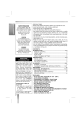


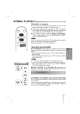

REAR
VIEW
5
INTRODUCTION
CHANNEL
32
40
RF
OUT
AERIAL
DC
IN
12V
AUDIO VIDEO
OUT
IN
+
POWER
CORD
Connect
to
any
100-240V,
50/60Hz
AC
outlet.
RF
CHANNEL
CONTROL
Turn
this
control
to
set
the
video
channel
(CH32-CH40)
correctly
(whichever
is
not
being
used
in
your
area).
AERIAL
IN
TERMINAL
Connect
the
external
antenna
to
this
terminal.
RF
OUT
ANTENNA
TERMINAL
Connect
this
terminal
to
the
AERIAL
antenna
terminal
on
the
back
of
the
TV.
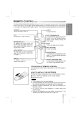
If
this
unit
is
connected
to
the
TV
via
the
supplied
coaxial
con-
nector
cable,
the
video
channel
will
have
to
be
set.
(see
page
6)
Setting
the
video
channel
with
playback
1
The
output
channel
of
the
VCP
is
set
at
UHF
channel
32.
2
Turn
on
the
TV
set
and
the
VCP.
3
Insert
a
pre-recorded
cassette
and
begin
playback.
4
Select
the
correct
channel
(32)
on
your
TV
set.
And
then
you
will
see
the
picture
being
played
in
VCP.
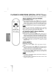
Changing
the
transmitter
channel
If
channel
32
is
already
occupied
at
your
TV
set,
or
if
the
picture
is
distorted,
you
can
change
the
transmitter
channel
of
the
VCP.
Select
an
undistorted
channel
between
32
and
40
on
your
TV
set
and
store
it.
Use
a
small
screwdriver
to
turn
slowly
the
CHANNEL
control
on
the
rear
of
the
VCP,
until
you
are
satisfied
with
the
picture
quality.
CHANNEL
3240
RF.OUT
AERIAL
DC
IN
12V
AUDIO
VIDEO
OUT
IN
+
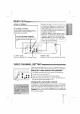
VIDEO
CHANNEL
SETTING
If
you
connect
a
monitor
or
a
TV
set
equipped
with
audio
and
video
sockets,
this
adjustment
will
not
be
necessary.
Consult
the
operating
instructions
of
your
TV
set.
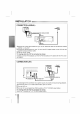
AUDIO
OUT
JACK;
Connect
this
terminal
to
the
audio
input
terminal
on
an
external
unit
(Audio
System,
TV/Monitor,
Another
VCR).
VIDEO
OUT
JACK;
Connect
this
terminal
to
the
video
input
terminal
on
an
external
unit
(TV/Monitor,
Another
VCR).
AUDIO
IN
JACK;
Connect
the
audio
output
cable
from
an
external
unit
(Audio
System,
TV/Monitor,
Another
VCR)
to
this
terminal.
VIDEO
IN
JACK;
Connect
the
video
output
cable
from
an
external
unit
(TV/Monitor,
Another
VCR)
to
this
terminal.
DC
INPUT
JACK
Input
from
optional
DC
12V
power
source.