User’s Guide W2600V Make sure to read the Important Precautions before using the product. Keep the User's Guide(CD) in an accessible place for future reference. See the label attached on the product and give the information to your dealer when you ask for service.
Important Precautions This unit has been engineered and manufactured to ensure your personal safety, however improper use may result in potential electrical shock or fire hazards. In order to allow the proper operation of all safeguards incorporated in this display, observe the following basic rules for its installation, use, and servicing. On Safety Use only the power cord supplied with the unit.
Important Precautions Do not use this display near water such as near a bathtub, washbowl, kitchen sink, laundry tub, in a wet basement, or near a swimming pool. Displays are provided with ventilation openings in the cabinet to allow the release of heat generated during operation. If these openings are blocked, built-up heat can cause failures which may result in a fire hazard. Therefore, NEVER: Block the bottom ventilation slots by placing the display on a bed, sofa, rug, etc.
Connecting the Display Before setting up the monitor, ensure that the power to the monitor, the computer system, and other attached devices is turned off. Connecting the stand base or Removing the stand base 1. Place the monitor with its front facing downward on a cushion or soft cloth. 2. Align the hooks on the Stand Body with the matching slots in the Stand Base. 3. Insert the hooks into slots.
Connecting the Display 4. Attach the monitor to the Stand Base by turning the screw to the right. Screw : Turn the screw by using the screw handle. 5. Lift and turn the monitor to face towards the front after the connection is made to the female part of the cable you're attaching. 6. Take the screw out by turning to the left to separate the monitor and Stand Base. Important This illustration depicts the general model of installation. Your monitor may differ from the items shown in the picture.
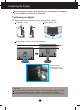
Connecting the Display Before setting up the monitor, ensure that the power to the monitor, the computer system, and other attached devices is turned off. Positioning your display 1. Adjust the position of the panel in various ways for maximum comfort. Tilt Range : -5˚~20˚ Swivel Range : 350˚ Height Range : maximum 3.94 inches (100.0mm) 100.0mm * Please be sure to remove the Locking pin to adjust the height.
Connecting the Display Using the Computer 1. Make sure to turn off the computer and product. Connect signal input cable 1 and power cord 2 in order, then tighten the screw of the signal cable. A Connect DVI(Digital signal) Cable B Connect D-sub(Analog signal) Cable (PC) C Connect D-sub(Analog signal) Cable (Mac) D Connect HDMI Cable NOTE This is a simplified representation of the rear view. This rear view represents a general model; your display may differ from the view as shown.
Connecting the Display 2. Touch the power button on the front of panel to turn the power on. When monitor power is turned on, the 'Self Image Setting Function' is executed automatically. (Only to the D-sub signal cable input (RGB)) Power button NOTE 'Self Image Setting Function'? This function provides the user with optimal display settings.When the user connects the monitor for the first time, this function automatically adjusts the display to optimal settings for individual input signals.
Connecting the Display Connecting the USB(Universal Serial Bus) Cable "USB (Universal Serial Bus)" is an innovation in connecting your different desktop peripherals conveniently to your computer. By using the USB, you will be able to connect your mouse, keyboard, and other peripherals to your display instead of having to connect them to your computer. This will give you greater flexibility in setting up your system.
Connecting the Display To arrange the cables Connect the power cord and the signal cable as shown in the figure and then fix them to the cable holders 1 and 2. 1. 2. Please insert the cable holder1 into the hole. Please put the power cord and the signal cable in the cable holder 1. Cable holder 1 3. Please put the power cord and the signal cable in the cable holder 2. While pressing the bottom of cable holder 2 with one hand, pull the top of it with the other hand as shown in the picture.
Control Panel Functions Front Panel Controls Button Button MENU Button Use this button to enter EZ ZOOMING, 4:3 IN WIDE, PHOTO EFFECT, SOUND items, for more information, refer to page 15 ~ 16. Use this button to enter On Screen Display Sub-menu to adjust BRIGHTNESS directly. Use this button to enter or exit from the On Screen Display. OSD LOCKED/UNLOCKED This function allows you to lock the current control settings, so that these settings are not inadvertently changed.
Control Panel Functions Buttons Use these buttons to select or adjust functions in the On Screen Display. For more information, refer to page 21~22. (SOURCE Hot key) AUTO/SET Button When 2 sets of computers are connected, you can select the input signal you want (RGB/DVI/HDMI). The default input signal is RGB. INPUT RGB DVI HDMI Use this button to enter a selection in the On Screen Display.
On Screen Display (OSD) Control Adjustment Screen Adjustment Making adjustments to the image size, position and operating parameters of the display is quick and easy with the On Screen Display Control system. A short example is given below to familiarize you with the use of the controls. The following section is an outline of the available adjustments and selections you can make using the OSD. NOTE Allow the display to stabilize for at least 30 minutes before making image adjustments.
On Screen Display(OSD) Selection and Adjustment The following table indicates all the On Screen Display control, adjustment, and setting menus.
On Screen Display(OSD) Selection and Adjustment You were introduced to the procedure of selecting and adjusting an item using the OSD system. Listed below are the icons, icon names, and icon descriptions of the all items shown on the Menu. Touch the MENU Button, then the main menu of the OSD appears.
On Screen Display(OSD) Selection and Adjustment The OSD screen will appear when you touch the bottom of the monitor. button on the left SOUND Main menu M E N U : Exit , : Move AUTO/SET : Select Description To select the adjust the resolution. When you select EZ ZOOMING in OSD, display resolution goes one step down so characters and images look bigger. When you select EZ ZOOMING once again, it goes back to the original resolution.
On Screen Display(OSD) Selection and Adjustment Main menu Description To select the color of the screen. PHOTO EFFECT • NORMAL : The PhotoEffect function is disabled. • GAUSSIAN BLUR : This option is to add the effect to the screen that the dark and sharp image becomes brighter and more blurred. • SEPIA : This option changes the screen to be Sepia tone. The Sepia tone is brown color tone. • MONOCHROME : This option changed the screen to be Gray tone.
On Screen Display(OSD) Selection and Adjustment Main menu Sub menu Description PICTURE RGB/DVI input BRIGHTNESS To adjust the brightness of the screen. CONTRAST To adjust the contrast of the screen. GAMMA Set your own gamma value. : -50 / 0 / 50 On the monitor, high gamma values display whitish images and low gamma values display high contrast images. BLACK LEVEL You can set the offset level. If you select 'HIGH', the screen will be bright and if you select ‘LOW’, the screen will be dark.
On Screen Display(OSD) Selection and Adjustment Main menu Sub menu Description TRACKING HORIZONTAL To move image left and right. VERTICAL To move image up and down. CLOCK To minimize any vertical bars or stripes visible on the screen background. The horizontal screen size will also change. PHASE To adjust the focus of the display. This item allows you to remove any horizontal noise and clear or sharpen the image of characters. SHARPNESS To adjust the clearness of the screen.
On Screen Display(OSD) Selection and Adjustment Main menu Sub menu Description LANGUAGE To choose the language in which the control names are displayed. OSD POSITION To adjust position of the OSD window on the screen. WHITE BALANCE If the output of the video card is different the required specifications, the color level may deteriorate due to video signal distortion.
On Screen Display(OSD) Selection and Adjustment Main menu Sub menu Description PIP PIP ON/OFF PIP ON/OFF To select PIP on or off. * It supports only for HDMI input in RGB (D-sub analog signal) mode. * The combinations of main screen and sub-screen (PIP) available are as shown below: ON Main screen RGB DVI HDMI RGB X X X DVI X X X HDMI O X X Sub-screen (PIP) MENU : Exit : Adjust : Adjust AUTO/SET : Select another sub-menu PIP POSITION Select the PIP display location.
On Screen Display(OSD) Selection and Adjustment The OSD screen will appear when you touch the button on the left bottom of the monitor. These features let you easily select the best desired image condition optimized to the environment (ambient illumination, image types etc). Menu Name MENU : Exit , : Move SET : Select Icons Sub-menu Name Main menu Sub menu MOVIE Description Select this when you are watching a video or movie.
On Screen Display(OSD) Selection and Adjustment Main menu Sub menu Description RGB/DVI input DEMO This is used for advertising in the store. The screen will be divided to show the standard mode on the left and video mode on the right so that the consumers can check the difference after applying the video mode. HDMI input SPORTS Select this when you watching general sports. USER You can manually adjust brightness, ACE or RCM (only for RGB/DVI input), HUE or SATURATION (only for HDMI input).
Troubleshooting Check the following before calling for service. No image appears ● Is the power cord of the • Check and see if the power cord is connected properly to the power outlet. display connected? ● Is the power indicator light on? • Touch the Power button. ● Is the power on and the • Adjust the brightness and the contrast.
Troubleshooting Display image is incorrect ● Display Position is incorrect. • Touch the AUTO/SET button to automatically adjust your display image to the ideal setting. If the results are unsatisfactory, adjust the image position using the H position and V position icon in the on screen display. ● On the screen background, vertical bars or stripes are visible. • Touch the AUTO/SET button to automatically adjust your display image to the ideal setting.
Troubleshooting Display image is incorrect ● The screen color is mono or abnormal. • Check if the signal cable is properly connected and use a screwdriver to fasten if necessary. • Make sure the video card is properly inserted in the slot. • Set the color setting higher than 24 bits (true color) at Control Panel - Settings. ● The screen blinks. • Check if the screen is set to interlace mode and if yes, change it to the recommend resolution.
Specifications Display 26 inches (64.868cm) Flat Panel Active matrix-TFT LCD Anti-Glare coating Visible diagonal size : 64.868 cm 0.2865 mm pixel pitch Sync Input Horizontal Freq. Vertical Freq. Input Form 30 - 83 kHz (Automatic) 56 - 75 Hz (Automatic) Separate Sync. SOG (Sync On Green) Digital(HDCP) Video Input Signal Input Input Form 15 pin D-Sub Connector DVI-D Connector (Digital), HDMI RGB Analog (0.
Specifications Stand Base Attached ( Power cord Wall-outlet type or PC-outlet type USB Standard USB 2.0, Self-Power Data Rate Max 480 Mbps ), Detached ( O ) Power Consumption Max 2.5W x 4 NOTE Information in this document is subject to change without notice.
Specifications Preset Modes (Resolution) - D-sub(Analog) / DVI(Digital) INPUT Display Modes (Resolution) VGA VESA VESA VGA VESA VESA VESA VESA VESA VESA VESA VESA VESA VESA VESA VESA VESA 1 2 3 4 5 6 7 8 9 10 11 12 13 14 15 16 *17 Horizontal Freq. (kHz) 640 x 480 640 x 480 720 x 480 720 x 400 800 x 600 800 x 600 1024 x 768 1024 x 768 1152 x 864 1280 x 768 1280 x 768 1280 x 1024 1280 x 1024 1600 x 1200 1680 x 1050 1680 x 1050 1920 x 1200 31.469 37.500 35.162 31.500 37.879 46.875 48.363 60.023 67.500 47.
Installing the Wall mount plate This monitor satisfies the specifications of the Wall mount plate or the interchange device. 1. After moving the product to face downward, make sure to place it on a soft cloth or a cushion to avoid surface damage. 2. Separate the head and the stand with the use of a screwdriver. 3. Install the Wall mount plate. Wall mount plate(Separate purchase) This is stand-type or wall mount type and is connectable with Wall mount plate.
Digitally yours