en-us_main.book.book Page 1 Monday, June 5, 2023 5:24 PM INSTALLATION MANUAL COMBINATION WALL OVEN Read this installation manual thoroughly before installing the appliance and keep it handy for reference at all times. ENGLISH WCES6428*, WCEP6427*, WCEP6423* MFL51224814 Rev.05_060823 www.lg.com Copyright © 2021-2023 LG Electronics Inc. All Rights Reserved.
en-us_main.book.
en-us_main.book.book Page 3 Monday, June 5, 2023 5:24 PM IMPORTANT SAFETY INSTRUCTIONS 3 IMPORTANT SAFETY INSTRUCTIONS Safety Messages Your safety and the safety of others are very important. We have provided many important safety messages in this manual and on your appliance. Always read and follow all safety messages. This is the safety alert symbol. This symbol alerts you to potential hazards that can kill or injure you and others.
en-us_main.book.book Page 4 Monday, June 5, 2023 5:24 PM 4 INSTALLATION INSTALLATION Before Installing Proper Location and Dimensions CAUTION • The cabinet base platform must be able to support 202 lbs (92 kg) for this appliance. If the cabinet does not have a solid bottom, two braces or runners must be installed level with the bottom of the cutout to support the weight of the appliance. Make sure the base is level and the front of the cabinet is square.
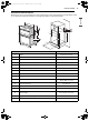
en-us_main.book.book Page 5 Monday, June 5, 2023 5:24 PM INSTALLATION 5 Dimensions and Clearances Measure the current cutout dimensions and compare them to the cutout dimensions shown below. Little or no cabinet work may be necessary. The image may differ from the actual model. ENGLISH G P F A I D E H J O N K B C List M L Dimensions A Height 43 13/16" (111.3 cm) B Width 29 3/4" (75.5 cm) C Depth 23 3/8" (59.3 cm) D Height (standard installation) E Height (power cord) 25 7/8" (65.
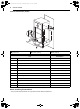
en-us_main.book.book Page 6 Monday, June 5, 2023 5:24 PM 6 INSTALLATION Cutout Dimensions (Flush) K L a Junction box b Conduit opening c Cleat (Spacer) List Dimensions A Cutout width B Cleat (spacer) inset from front of cabinet 1 3/8" (3.5 cm) C Cleat (spacer) width 3/16" (0.5 cm) D Cleat (spacer) depth 1" (2.5 cm) E Depth of open door 23" (58.4 cm) F Bottom of cutout from floor 12” (30.5 cm) G Cutout depth 25" (63.5 cm) H Cutout height 44" (111.
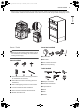
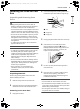
en-us_main.book.book Page 7 Monday, June 5, 2023 5:24 PM INSTALLATION 7 • Remove one screw from the left and right sides as shown. These screw holes will be used to mount the cover brackets. Install the cover brackets on the sides of the oven with the provided self-tapping screws. ENGLISH Parts / Tools Parts Not Provided WARNING • Mounting screws must be used. Failure to do so can result in the oven falling out of the cabinet causing serious injury.
en-us_main.book.book Page 8 Monday, June 5, 2023 5:24 PM 8 INSTALLATION NOTE • Observe all governing codes and ordinances. • Have the installer show you the location of the circuit breaker or fuse. Mark it for easy reference. • As when using any appliance generating heat, there are certain safety precautions you should follow. • Be sure your appliance is installed and grounded properly by a qualified installer or service technician.
en-us_main.book.book Page 9 Monday, June 5, 2023 5:24 PM INSTALLATION Installing the Oven and Test Run 2 9 Unlock the hinge locks, rotating them as far toward the open door frame as they will go. ENGLISH Unpacking and Removing Oven Doors WARNING • Keep packing materials out of the reach of children. Packaging material can be dangerous for children. There is a risk of suffocation. • You should use two or more people to move and install the appliance.
en-us_main.book.book Page 10 Monday, June 5, 2023 5:24 PM 10 INSTALLATION Electrical Requirements Ensure that dedicated circuit protection is prepared as recommended and that the appliance is grounded properly. This wall oven must be electrically grounded in accordance with local codes or, in their absence, with the National Electrical Code ANSI/NFPA No.70- latest edition* in United States, or with CSA Standard C22.1-1982 and C22.2 No.
en-us_main.book.book Page 11 Monday, June 5, 2023 5:24 PM INSTALLATION 11 the instructions for a 4-wire circuit connection. WARNING • The middle (neutral or ground) wire, which is white, of a 3-wire power cord or a 3-wire conduit has to be connected to the middle post of the main terminal block. The remaining two wires of the power cord or conduit have to be connected to the outside posts of the main terminal connection block.
en-us_main.book.book Page 12 Monday, June 5, 2023 5:24 PM 12 INSTALLATION 4 Connect the oven red wire to the branch circuit red (L2) wire in accordance with local codes, using a wire nut. 5 Connect the oven black wire to the branch circuit black (L1) wire in accordance with local codes, using a wire nut. 6 Install the junction box cover. use a minimum of 4 screws, one on each side in both the upper and lower ovens.
en-us_main.book.book Page 13 Monday, June 5, 2023 5:24 PM INSTALLATION 13 NOTE Common 5 1 Turn on the power supply. The initial signal sound will be heard. 2 Check the operation of the broil mode. Close the oven door. • When the oven is set to broil, the upper element in the oven should become red. After a few minutes, partially open the oven door. You should feel heat from the oven. Touch Stop.
en-us_main.book.book Page 14 Monday, June 5, 2023 5:24 PM 14 INSTALLATION Lower Oven 1 Check the operation of the burner for each convection mode. • After setting the oven to 350 ℉ / 177 ℃ for each convection mode, the back element should light up and the fan inside the oven should come on with the door closed. NOTE • A small amount of smoke and odor may be noticeable during the initial break-in period.
es-us_main.book.book Page 16 Monday, June 5, 2023 5:19 PM LG Customer Information Center For inquiries or comments, visit www.lg.com or call: 1-800-243-0000 1-888-542-2623 U.S.A. CANADA Register your product Online! www.lg.