MultiSITE CRC1 Series Controllers INSTALLATION MANUAL 09-26-2017 Occ Auto Heat 2:43 PM Auto Indoor °F 74° Humidity 66 % PREMTBVC0 – MultiSITE CRC1 PREMTBVC1 – MultiSITE CRC1+ 78 68
PROPRIETARY DATA NOTICE This document, as well as all reports, illustrations, data, information, and other materials are the property of LG Electronics U.S.A., Inc., and are disclosed by LG Electronics U.S.A., Inc., only in confidence. Do not throw away, destroy, or lose this manual. Please read carefully and store in a safe place for future reference. Content familiarity required for proper installation and operation.
TABLE OF CONTENTS Safety Instructions................................................................................................4 Introduction...........................................................................................................7 Controller Overview..............................................................................................8 Home Screen.................................................................................................................
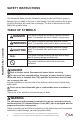
SAFETY INSTRUCTIONS The instructions below must be followed to prevent product malfunction, property damage, injury or death to the user or other people. Incorrect operation due to ignoring any instructions will cause harm or damage. The level of seriousness is classified by the symbols below. MultiSITE CRC 1 Controller TABLE OF SYMBOLS DANGER This symbol indicates an imminently hazardous situation which, if not avoided, will result in death or serious injury.
SAFETY INSTRUCTIONS Do not install the MultiSITE Controller unit if it will be exposed to rain or other precipitation. Do not install the unit in a location exposed to open flame or extreme heat. Do not touch the unit with wet hands. There is risk of fire, electric shock, physical injury and/or death. Replace all control box and panel covers. If cover panels are not installed securely, dust, water and animals may enter the unit, causing fire, electric shock, and physical injury or death.
SAFETY INSTRUCTIONS Note: Clean up the site after all procedures are finished, and check that no metal scraps, screws, or bits of wiring have been left inside or surrounding the controller or indoor units. Provide power to the outdoor unit compressor crankcase heaters at least six (6) hours before operation begins. Starting operation with a cold compressor sump(s) may result in severe bearing damage to the compressor(s). Keep the power switch on during the operational season.
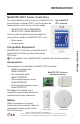
INTRODUCTION MultiSITE CRC1 Series Controllers This manual describes how to install the LG MultiSITE Com- Typical MultiSITE mercial Remote Controllers (CRC) 1 and the accessories CRC1 Controller described below.
CONTROLLER OVERVIEW Home Screen The controller home screen is shown and described below.
CONTROLLER INSTALLATION Selecting Installation Location The room temperature sensor is inside the controller, so the installation location is critical to proper system operation. Install the controller in a location away from direct sunlight, high humidity, and direct flow of hot or cold air. Install the controller on a flat, clean wall surface approximately 5 ft above the floor in an area with good circulation and average temperature.
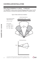
CONTROLLER INSTALLATION Selecting Installation Location – continued The PREMTBVC1 contains a passive infrared (PIR) sensor. Refer to Figure 2 for PIR sensor information to consider when selecting the PREMTBVC1 installation location. Figure 2: Motion (PIR) Sensor Installation Horizontal Angles (Typical) Recommended installation height for PIR sensor: / 1.5 m/s Transverse motion: 4-5 ft/s 4 - 5 ft. / 1.2-1.5 m MultiSITE CRC 1 Controller Sensor Ranges A = 20 ft. / 6.1 m B = 14 ft. / 4.3 m C = 11 ft.
CONTROLLER INSTALLATION Installing the Controller Follow this procedure to install the controller. Note: 1. Remove security screw (if any) on bottom of Remote Controller cover (Figure 3). 2. Read FCC ID and IC label installed in cover before installing any wireless product. Figure 3: Open Cover 3. Ensure correct side of base faces up. 4. Pull cable 6 inches out from wall. 5. Align base and mark location of two mounting holes on wall (Figure 4). 6. Install anchors in wall. 7.
CONTROLLER INSTALLATION Installing the Controller – continued Figure 4: Install Base 8. Insert screws in mounting holes on each side of base. 10. If using Extension Cable PZCWRC1, carefully cut off the white Molex connector and strip each wire 1/4 inch from end. Common Signal 12VDC Figure 5: Controller Wiring YL RD 4 5 6 12 Not used Not used Not used BACnet Common BACnet- 13 14 15 BACnet+ MultiSITE CRC 1 Controller 9.
CONTROLLER INSTALLATION Installing the Controller – continued 11. Insert each wire in terminal block according to wiring diagram (Figure 5). Table 1 lists the function of all terminal connections. Figure 6: Reinstall Cover 12. Carefully push excess cable back into hole. 13. Gently align cover to top of base and snap in place from bottom (Figure 6). 14. Install security screw.
CONTROLLER SETUP Controller Setup This section contains a brief overview of MultiSITE controller operation. Refer to the MultiSITE CRC Series User Manual for more information.
CONTROLLER SETUP Setpoint Adjustment Setpoints can be modified in three different ways when in Auto Mode: Cooling Setpoint change, Heating Setpoint change or Cooling/Heating Setpoint change. 2:43 PM 09-26-2017 Occ Auto Cool Cooling Setpoint °F 75.0 Humidity 45 % Normal temperature display resumes after the setpoint is adjusted and the actual occupied cooling setpoint is displayed in the setpoint bar.
CONTROLLER SETUP Setpoint Adjustment – continued 09-26-2017 Occ Auto Heat 2:43 PM Auto Indoor °F MultiSITE CRC 1 Controller 74° Humidity 66 % 78 68 Automatic Heating / Cooling mode In automatic mode, the setpoint displayed at the top of the set point bar located directly under the blue line represent the actual occupied cooling setpoint. During occupied setpoints adjustment, the large digits are temporarily used to display the occupied “Cooling Setpoint” or occupied “Heating Setpoint.
ACCESSORIES INSTALLATION ZigBee Pro Wireless Module Follow this procedure to install the optional ZigBee Pro wireless module (model ZVRCZPWC1. This wireless module is required for the controller to communicate with the optional wireless sensors. Figure 8: ZigBee Pro Wireless Module Installation Manual 1. Remove security screw (if any) on bottom of Remote Controller cover. 2. Open unit by pulling on bottom side of Remote Controller (Figure 9). 3.
MultiSITE CRC 1 Controller ACCESSORIES INSTALLATION 6. Gently press the ZigBee Pro module into the Remote Controller’s Figure 10: Install ZigBee Pro Wireless Module motherboard until it fits snugly in place. Do not press too hard to avoid damage to ZigBee Pro module. 7. Carefully replace Remote Controller’s motherboard into casing. 8. Carefully align cover to top of base and snap in place from bottom (Figure 11). 9. Install security screw.
ACCESSORIES INSTALLATION Ceiling Motion Sensor Follow this procedure to install the optional wireless ceiling motion sensor. Figure 12: Ceiling Motion Sensor Consider the following location constraints before installing a ceiling mounted sensor: Do not install on a metal surface. Do not install in areas with a direct heat source. • Do not install near any air discharge grill. • Do not install in areas exposed to direct sunlight. • Ensure ceiling surface is flat and clean.
ACCESSORIES INSTALLATION Installation Sequence Complete the following steps (in this order) to correctly install the ceiling mounted motion sensor: • • • • Figure 14: Remove Mounting Plate Install batteries. Pair sensor with MultiSITE Controller. Verify sensing motion. Install sensor to ceiling surface. MultiSITE CRC 1 Controller Install Batteries 1. Remove mounting plate by rotating housing counter-clockwise (Figure 14). 2. Install two AAA batteries in Sensor Housing (Figure 15).
ACCESSORIES INSTALLATION Install Ceiling Motion Sensor Installation Manual 1. Consider sensor placement conditions before installing sensor. Refer to “Sensor Placement” on page 19. 2. Secure mounting plate to overhead surface with two screws (Figure 17). Ensure screws are tight and mounting plate does not move easily. Do not torque screws. Figure 17: Installing Sensor on Ceiling 3. Set sensor housing assembly on mounting plate (Figure 17). 4.
ACCESSORIES INSTALLATION Wall Mounted Motion Sensor Follow this procedure to install the optional wireless wall mounted motion sensor. Figure 19: Wall Mounted Motion Sensor Consider the following location constraints before installing a ceiling mounted sensor: Do not install on a metal surface. Do not install in areas with a direct heat source. • Do not install near any air discharge grill. • Do not install in areas exposed to direct sunlight. • Ensure wall surface is flat and clean.
ACCESSORIES INSTALLATION Installation Sequence Complete the following steps (in this order) to correctly install the ceiling mounted motion sensor: • • • • • Figure 21: Remove Sensor Cover Install battery. Pair sensor with MultiSITE Controller. Remove plastic pull tab. Verify sensing motion. Install sensor to ceiling surface. Install Battery Verify Sensing Motion Figure 22: Install Battery Installation Manual 1. Use a flathead screwdriver to carefully pry cover away from motion sensor (Figure 21). 2.
ACCESSORIES INSTALLATION Install Wall Mounted Motion Sensor MultiSITE CRC 1 Controller Install the motion sensor to the desired location. The motion sensor can be installed vertically, horizontally, or upside down on a flat surface or in a corner. 1. Consider sensor placement conditions before installing sensor. Refer to “Sensor Placement” on page 22. 2. Affix two-sided tape to desired installation location (Figure 24). 3. Position motion sensor on twosided tape and press firmly to secure in place. 4.
ACCESSORIES INSTALLATION Door/Window Sensor Figure 26: Door/Window Sensor Follow this procedure to install the optional door/window sensor. Consider the following location constraints before installing a door/window sensor: Do not install a on metal surface. Do not install in areas with a direct heat source. • Do not install near any air discharge grill. • Do not install in areas exposed to direct sunlight. • Ensure mounting surface is flat and clean.
ACCESSORIES INSTALLATION Installation Sequence Complete the following steps (in this order) to correctly install the door/window sensor: • • • • • • Install batteries. Pair sensor with MultiSITE Controller. Remove plastic pull tab. Install sensor housing. Install magnet. Install sensor. MultiSITE CRC 1 Controller Install Battery 1. Pull tab and slide open housing of door/window sensor to access battery (Figure 28). 2. Install one CR2032 battery in the housing (Figure 29).
ACCESSORIES INSTALLATION surface and securely affixed to surface. 2. Position sensor housing on two sided tape and press firmly to secure in place. 3. Ensure the sensor is paired. If necessary, refer to “ZigBee Pro Quick Setup” on page 29. 4. Slide the sensor into the housing. Figure 30: Install Sensor with Tape To install with screws: 1. Secure the sensor housing to the desired location with two screws (Figure 31). Ensure screws are tight and sensor does not move easily. Do not torque screws. 2.
ACCESSORIES INSTALLATION Sensor Functions Figure 33 shows the location of the function button on the sensor module. Refer to “Table 2: Function Button and LED Indicators” on page 30 for information on using this button and the LED indicator to set up sensor module operation. Figure 32: Remove Screw Tab if Desired MultiSITE CRC 1 Controller Figure 33: Function Button and LED Test Sensor with Controller Refer to “ZigBee Pro Quick Setup” on page 29 for information on how to test sensor operation.
ZIGBEE SETUP ZigBee Pro Quick Setup This quick set-up describes how to pair a ZigBee sensor with a Remote Controller. Please see ZigBee Configuration section of the MultiSITE CRC1 User Interface Guide if this is the first time a sensor is being paired with the remote controller for proper configuration of the ZigBee Wireless network. Installation Manual 1. Go to first Zone screen in Wireless Ecosystem section of MultiSITE CRC1 Series Remote Controller's interface and set “Permit join” to On.
ZIGBEE SETUP Table 2: Function Button and LED Indicators BUTTON LED ACTION MultiSITE CRC 1 Controller 2 times GG GGGG 4 Times 8 Times GGGGGGGG 10 Times GGGGGGGGGG G = Green Y = Yellow R = Red 30 Network Status Network Join Forced Re-Join Network leave and join a new Network No Action Power Up LED DESCRIPTION GGG Joined RRR Not Joined YYY Re-Join in Process YRY Searching for Network YGY Device Being Configured GGG Device Joined RRR Device Failed to Join YYY Re-Join, Searching
BACNET MS/TP SETUP BACnet MS/TP Quick Setup This quick set-up describes how to set-up the BACnet* MS/TP with a Remote Controller. Please see BACnet MS/TP Configuration section of the MultiSITE CRC1 User Interface Guide for complete instructions of the configuration of the BACnet MS/TP network. Installation Manual 1. Touch and hold top of the screen for 3 seconds to enter Configuration settings as illustrated in Figure 7 on page 14. 2.
SPECIFICATIONS MultiSITE CRC 1 Controller PREMTBVC0 and PREMTBVC1 Dimensions • Height: 4.72 in • Width: 3.39 in • Depth: 1.06 in Power Requirements • 12 VDC, 2.34W, supplied by IDU Operating Conditions • 32 °F - 122 °F • 0% - 95% R.H. non-condensing Storage Conditions • -22 °F - 122 °F • 0% - 95% R.H. non-condensing Temperature Sensor • Local 10 K NTC type 2 thermistor Temperature Sensor Resolution • ± 0.2 °F Temperature Control Accuracy • ± 0.
SPECIFICATIONS Installation Manual Room Temperature Display Range • 33 °F - 103 °F Deadband (2 set point) for Room Temperature control • Cooling & Heating: Default: 5°F Wire Gauge • 22 gauge or larger Approximate Shipping Weight • 0.75 lb Safety Standards All Models • LVD Directive 2006/95/EC • EN 60950-1:2006/A2:2013 • UL 873 CSA C22.2 No.
FCC Notice This equipment has been tested and found to comply with the limits for a Class A digital device, pursuant to part 15 of the FCC Rules. These limits are designed to provide reasonable protection against harmful interference when the equipment is operated in a commercial environment. This equipment generates, uses, and can radiate radio frequency energy and, if not installed and used in accordance with the instruction manual, may cause harmful interference to radio communications.
Installation Manual LG Customer Information Center, Commercial Products 1-888-865-3026 USA Follow the prompts for commercial A/C products and parts. Due to our policy of continuous product innovation, some specifications may change without notification. ©LG Electronics U.S.A., Inc., Englewood Cliffs, NJ. All rights reserved. “LG” is a registered trademark of LG Corp.
LG Electronics Commercial Air Conditioning Division 4300 Northpoint Parkway Alpharetta, Georgia 30022 www.lghvac.