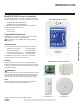
MultiSITE CRC1 Series Controllers USER INTERFACE GUIDE 09-26-2017 Occ Auto Heat 2:43 PM Auto Indoor °F 74° Humidity 66 % PREMTBVC0 – MultiSITE CRC1 PREMTBVC1 – MultiSITE CRC1+ 78 68
PROPRIETARY DATA NOTICE This document, as well as all reports, illustrations, data, information, and other materials are the property of LG Electronics U.S.A., Inc., and are disclosed by LG Electronics U.S.A., Inc., only in confidence. Do not throw away, destroy, or lose this manual. Please read carefully and store in a safe place for future reference. Content familiarity required for proper installation and operation.
TABLE OF CONTENTS Safety Instructions........................................................................................................4 Introduction...................................................................................................................7 MultiSITE CRC1 Series Controllers..........................................................7 Compatible Equipment..............................................................................7 Accessories...................................
SAFETY INSTRUCTIONS The instructions below must be followed to prevent product malfunction, property damage, injury or death to the user or other people. Incorrect operation due to ignoring any instructions will cause harm or damage. The level of seriousness is classified by the symbols below. TABLE OF SYMBOLS DANGER This symbol indicates an imminently hazardous situation which, if not avoided, will result in death or serious injury.
SAFETY INSTRUCTIONS MultiSITE Controller is for use with select LG commercial air conditioning systems only. Do not attempt to use MultiSITE Controller with any other type of system. Refer to the compatible equipment list in this manual. There is risk of equipment damage or degraded performance Do not cut, lengthen or shorten the cable between the MultiSITE Controller unit and the indoor unit.
MultiSITE CRC 1 Controller 6 Due to our policy of continuous product innovation, some specifications may change without notification. ©LG Electronics U.S.A., Inc., Englewood Cliffs, NJ. All rights reserved. “LG” is a registered trademark of LG Corp.
INTRODUCTION MultiSITE CRC1 Series Controllers This manual describes how to use the LG MultiSITE Commercial Remote Controllers (CRC) 1.
CONTROLLER OVERVIEW Home Screen The controller home screen is shown and described below.
CONTROLLER OVERVIEW Operation Mode Selecting modes available on this screen places the IDU in that mode and then the user will be returned to the home screen. Selecting the mode that is currently highlighted will maintain the current mode and return the user to the home screen. OPERATION MODE Heat Fan Auto User Interface Guide Cool Auto Dry Setback Due to our policy of continuous product innovation, some specifications may change without notification. ©LG Electronics U.S.A., Inc.
CONTROLLER OVERVIEW Adjusting Setpoints in Auto Mode Setpoints can be modified in three different ways when in Auto Mode: Cooling Setpoint change, Heating Setpoint change, or Cooling/Heating Setpoint change. 09-26-2017 Occ Auto Heat 2:43 PM Auto Indoor °F MultiSITE CRC 1 Controller 74° Humidity 66 % 78 68 Auto Mode, Cooling Cycle, Cooling Setpoint (Dual Setpoint setting) When in cooling cycle of Auto Mode, use the up and down arrows to raise or lower the cooling setpoint.
CONTROLLER OVERVIEW Setpoint Adjustment Setpoints can be modified in three different ways when in Auto Mode; Cooling Setpoint change, Heating Setpoint change or Cooling/Heating Setpoint change. 2:43 PM 09-26-2017 Occ Auto Cool Cooling Setpoint °F 74° 75.0 Occ Auto Heat Heating Setpoint °F 74° 75.
CONTROLLER OVERVIEW Using the Controller Configuration Screens Some of the buttons on the Home screen display configuration screens. Controller operating parameters can be set as necessary for your system. The figure below describes how to use the configuration screens. Screen Name 1/ 3 Z ig b e e C o n f ig u r a t io n MultiSITE CRC 1 Controller Controls The left side of the screen lists controls and monitored parameters. Back Button Tapping this button goes back one level in the screen hierarchy.
CONFIGURATION SCREENS Schedule Screen Press the Schedule button on the Home screen to display the Schedule Screen. There are different schedule setting screens, one for each day of the week (7 days) titled accordingly. Each can have different scheduled events where the room controller is set for set point, system mode, fan speed and occupancy status. Five (5) separate events can be configured per day. ****day S chedul e Tap the right-hand side button to enter the next screen.
CONFIGURATION SCREENS Daily Schedule Screens – continued Mo nd ay S ch ed u le 06:00AM H 74 / 70:O 05:00PM C 71 / 69:U 09:00PM Off --:-- MultiSITE CRC 1 Controller --:-Delete Co p y to To modify an existing event, tap either the left side control to edit the time or tap the right-hand side of the control to re-enter the event screen and make your desired changes.
CONFIGURATION SCREENS More Screens Press the More button on the Home screen to display the More screen. Language Use the up and down arrows to switch between English, French and Spanish M or e English Te m p U n i ts (1 2 ) ° F (1 ) Aux H e a t On O uts i d e A i r - Ve n t.
CONFIGURATION SCREENS More Screens – continued Press the right arrow button to display these screens. To adjust vane angle, user selects vane(s) by tapping vane icon at the top of the screen, adjusts vane angle by using up/down arrows and then selects Apply button. Note: Vane fixed angle control for multi-vane systems occurs in pairs. Refer to the Vane Fixed Angle screen.
CONFIGURATION SCREENS Installer Configuration Screens These screens are more commonly used during installation, system configuration, or troubleshooting than by an end user. There is no icon on the Home screen to access these configuration screens. You must press and hold the area of the screen indicated on the diagram below to access the first screen.
CONFIGURATION SCREENS Configuration Main Screens There are two main configuration screens as shown below. Press the left and right arrow buttons to move between these two screens. Press a button on a screen to display the parameter selections for that item.
CONFIGURATION SCREENS ZigBee Wireless System When ZigBee wireless sensors are set up to communicate with the controller, the functioning of each such sensor is described in a separate Zone screen, up to a maximum of 10 Zones. Press the left and right arrow keys to move between Zone screens. Select the appropriate type of sensor using the up and down arrow keys. Configuration 2/2 Enter ZigBee wireless Zone configuration settings.
CONFIGURATION SCREENS Building Manager Screens There are two main configuration screens as shown below. Press the left and right arrow buttons to move between these two screens. Press a button on a screen to display the parameter selections for that item. 1 /2 B ui l di ng M a na ge r D is p la y / Da t e & Ti m e MultiSITE CRC 1 Controller Customize Home View Hide On/Off, Mode, Schedule, More, Set Temp, Space Temp, Fan and Humidity options on home screen.
CONFIGURATION SCREENS Display/Date and Time Settings Press the Display / Date & Time button on the Building Manager screen to show the Display menu screen. Press the right arrow button on the Display menu screen to show the Date & Time screen.
CONFIGURATION SCREENS Display/Date and Time Settings – continued Press the right arrow button on the Display screen to show the screen below. The Clock settings screen allows the device’s internal time settings to be changed, including current time, standard day, month, year and weekday options, as well as the choice between a 12 hour AM / PM display or a 24 hour display. Using the Up and Down arrows adjust the Time, Year, Month and Day parameters.
CONFIGURATION SCREENS Filter Functions Press the Filter Functions button on the Building Manager screen to display the Filter Functions screen. The Filter Functions menu displays the time and alarm parameters. These cannot be adjusted by the user. Filter Functions Robot Cleaning Auto Filter Remain(Hrs) 108 108 Filter Alarm Filter OK The time is measured in hours. Maximum value is 2400.
CONFIGURATION SCREENS Setpoints Configuration Press the Setpoint Config button on the Building Manager Screen to display the Setpoints Configuration screen. Press the Single/Dual button to select single or dual setpoint operation. Setpoint Single / Dual 1/2 Single / Dual Dual SP(1) Press up or down arrow keys below to select between Single our Dual set point modes.
CONFIGURATION SCREENS Override Setup Press the Override Setup button on the Building Manager screen to display the Override Setup screen. The user can configure override settings including set points, system mode, fan speed and override duration. Override Operation Override mode can only be activated if the current system status is Unoccupied. If this condition is met, the controller will enter Override mode as soon as the user taps the screen the first time (from dim state).
CONFIGURATION SCREENS Setback Setup Press the Setback Setup button on the Building Manager screen to display the Setback Setup screen. Setback parameters including set points, system mode, and fan speed are configured on this screen. Setback Operation If the controller is in Setback mode and the user changes the Mode, Fan Speed or Set Points, the controller exits Setback mode and keeps settings as applied by the user until the next scheduled event occurs.
CONFIGURATION SCREENS Outdoor Unit Control Press the Outdoor Unit Control button on the Building Manager screen to display the Outdoor Unit Control screen. The Outdoor Unit Control lets you manage outdoor units through the controller interface. O ut d o o r U n i t C o n t r o l Snow R mvl(1) S mar t lo ad contr l N ormal(2) E co .
CONFIGURATION SCREENS Installer Press the Installer button on the Configuration screen to display the Installer screen. The Installer menu lists the controller’s setup parameters and the accessories menu. Installer General Settings Te m p e r a t u r e S e t t i n g s MultiSITE CRC 1 Controller Fan Settings Heat Settings Accessories Code Search Use the Up and Down arrows to choose an available Function Code and select the Code Search button to navigate to the screen where that function code resides.
CONFIGURATION SCREENS General Settings There are four Installer / General Settings screens. Press General Settings on the Installer screen to display the first General Settings screen. Press the right arrow on the screen to display screens 2, 3, and 4. This value will be used to decide if Auto mode appears in the Operation Mode screen and whether to show “Auto” text at the top of the Home screen during Auto operation mode. 1/4 Installer / General CC Add. Group(2) 0 CC Add.
CONFIGURATION SCREENS 3/4 Installer / General Use this function to enable or disable Group Control for the system. MultiSITE CRC 1 Controller Use this function to enable or disable Indoor Unit Auto Start. Test run(1) Co o l i n g (1) I DU Mode- M/ S (8) Master(1) G rp Cn trl F u n cs(19) Di sab l e(0) G uard Ti mer(33) 30 Mi n (2) I DU Auto S tart(39) E n ab l e(1) Configuration Parameters Default Value Using the Up and Down arrows select between Heating, Cooling or Off modes.
CONFIGURATION SCREENS Temperature Settings Press the Temperature Settings button on the Installer screen to display the Temperature Settings screen. Press the right arrow button to display the second page of the Temperature Settings screen. 1/ 2 Temperature Setti ngs 2 / 2 Te m p e r a t u r e S e t t i n g s Temp Sens Loc(4) RC(1) Heat. Therm(15) 4°F /7°F (2) Se t P oi nt P r e c . ( 1 7 ) 1°F(1) Cool.
CONFIGURATION SCREENS Fan Settings Press the Fan Settings button on the Installer screen to display the Fan Settings screen. Press the right arrow button to display the second page of the Fan Settings screen.
CONFIGURATION SCREENS Heat Settings Press the Heat Settings button on the Installer screen to display the Heat Settings screen. Heat Settings Use this function to enable or disable auxiliary heat control. Ex t Aux H eat(25) D isable(0) Au x He at C tr l(21) D isable(0) P r im He at C tr l(36) H P Fir st(0) Using the Up and Down arrows select between Disable, Non-Ducted and Ducted. Select between Primary Heat First and Primary Heat Last.
CONFIGURATION SCREENS Emergency Heater Settings Press the Emergency Heater button on the Heat Settings screen to display the Emergency Heater Settings screen.
CONFIGURATION SCREENS Accessories Press the Accessories button on the Installer screen to display the Accessories screen. Press the right arrow to display the second page of the Accessories screen. 1/2 Accessories This option enables the related control on the Filter Functions screen that controls Raise/Lower Grill functions. Disable(0) Dry cont. Au to (9 ) Auto Off(0) CN_EXT Cnfg (52) E mrg Alrm(5) Out.
CONFIGURATION SCREENS Accessories – continued MultiSITE CRC 1 Controller Configuration Parameters Default Value 36 Parameter Settings Dry Cont Enbl(41) Default value = Disabled(0) Choices: 0 = “Disable (0)” 1 = “Not Used (1)” 2 = “Enabled (2)” 3 = “Use CN_EXT (3)” Dry cont.
CONFIGURATION SCREENS BMS Configuration Press the BMS Config button on the Configuration screen to display the BMS Config screen. BMS Config B A Cn e t s e t t i n g s Zi g B e e C o n f i g User Interface Guide BACnet Settings Press the BACnet* settings button on the BMS Config screen to display the BACnet Network screen. Press the right arrow to display the BACnet Instance screen.
CONFIGURATION SCREENS BACnet Settings – continued Configuration Parameters Default Value Parameter Settings Communications Address MultiSITE CRC 1 Controller COM address Terminal Equipment Controller Networking address Default value = 254 Range is: 0 to 254 For BACnet MS/TP models, the valid range is from 0 to 253. Default value of 254 disables BACnet communication for the Controller.
CONFIGURATION SCREENS ZigBee Configuration Press the ZigBee* Config button on the BMS Config screen to display the ZigBee Configuration screen. 1/ 3 Z ig b e e C o n f ig u r a t io n 254 Node type Coord. Z i gb e e PA N ID 11 Z i gb e e c h a n n e l 15 Z i gb e e s h o r t 0x0000 Z i gb e e s t a t u s No NWK Configuration Parameters Default Value ZigBee Pro short address. The address is generated once the device joins a ZigBee network.
CONFIGURATION SCREENS ZigBee Configuration – continued Press the right arrow on the ZigBee Configuration screen to display the second page of the ZigBee Configuration screen. The blue fields indicate the controller is paired with a sensor.
CONFIGURATION SCREENS ZigBee Configuration – continued Press the right arrow on the ZigBee Configuration screen to display the third page of the ZigBee Configuration screen. 3/3 Zigbee configuration IEEE address 0x0000 Only last 4 digits in HEX show User Interface Guide Configuration Parameters Default Value IEEE address Default value = 0x0000 Parameter Settings The extended IEEE ZigBee node address is used to identify the device on the network.
CONFIGURATION SCREENS Basic Diagnostic Press the Basic Diagnostic Button on the Configuration screen to display the Basic Diagnostic screen. 1/ 6 Basi c Diag n o sti c Firmware revision of the controller MultiSITE CRC 1 Controller Pipe temperature configuration F irmw are rev. 1.0.5-7a9a ODU St a t u s On Pipe temp conf. On Outdoor Unit Status Press the right arrow on the Basic Diagnostic screen to display the next Basic Diagnostic screen.
CONFIGURATION SCREENS Basic Diagnostic – continued Press the right arrow on the Basic Diagnostic screen to display the next Basic Diagnostic screen. 3/6 Basic Di ag n o sti c Co o ling SP Max 99 °F Co o ling SP Min 50 °F He a t ing S P Max 90 °F He a t ing S P Min 40 °F User Interface Guide Press the right arrow on the Basic Diagnostic screen to display the next Basic Diagnostic screen.
CONFIGURATION SCREENS Basic Diagnostic – continued Press the right arrow on the Basic Diagnostic screen to display the next Basic Diagnostic screen. 5/6 Basic Di ag n o sti c MultiSITE CRC 1 Controller Screens 5/6 Basic Diagnostic and 6/6 Basic Diagnostic display a historical list of the 10 most recent error codes generated by the Indoor Unit. The most recent error code appears at the top of the list.
CONFIGURATION SCREENS Password Setup Press the Password Setup button on the Configuration screen to display the Password Setup screen. Password Setup Config password 0 User password 0 Config password Default value = 0 User Interface Guide Configuration Parameters Default Value Parameter Settings Config password This parameter sets a protective access password to prevent unauthorized access to the configuration menu parameters.
CONFIGURATION SCREENS Factory Default Answering Yes to both parameters and tapping ‘push to accept’ erases all values and sets the controller to factory default values. Note: Once in the Factory Default screen, if user proceeds with this step, all schedules and current controller settings, along with time and date will be cleared. There is no way to recover settings once a Factory Default has been performed.
CONFIGURATION SCREENS Relative Humidity Display Relative humidity is displayed on the MultiSITE CRC1+ controller only. Apart from the visual indication of relative humidity, this data is also available as a monitoring point via MSTP BACnet to be used by the user as desired. 09-26-2017 2:43 PM Occ Auto Heat Indoor °F 74° 75.0 Humidity User Interface Guide 45 % Relative humidity Time and Date Time and date are displayed at the top of the home screen.
CONFIGURATION SCREENS PIR (Motion Sensor) The MultiSITE CRC1+ version of the controller comes with an onboard PIR style motion sensor. If the sensor is enabled (installer configuration under Accessories), status from the PIR sensor will be used to control the operation of the IDU as follows: If the IDU status is currently Occupied and the onboard PIR goes Unoccupied, the IDU will operate according to the Setback values of the controller and will change its status to Unoccupied.
Who to call for assistance Freight Damage and Unit Replacements Missing Parts Freight Damage and Unit Replacements Received Wrong Indoor Unit Model Installation, Startup, and Commissioning Technical Assistance Your LG Manufacturer Representative Your LG Manufacturer Representative Your LG Manufacturer Representative Your LG Manufacturer Representative 1-888-865-3026 For warranty information, visit www.lghvac.com.
LG Electronics Commercial Air Conditioning Division 4300 Northpoint Parkway Alpharetta, Georgia 30022 www.lghvac.com LG Customer Information Center, Commercial Products 1-888-865-3026 USA Follow the prompts for commercial A/C products and parts.