
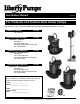
Install Instructions


©Copyright 2012 Liberty Pumps Inc. All rights reserved - 3 -
2. Sump Pit – All Models
1. A sump pit not less than 14” in diameter is recommended. On submersible pumps equipped with the vertical float
(models 237 and 247), a minimum 10” diameter pit is acceptable. A larger diameter pit is preferred as it allows for
longer pump cycling and reduced switch cycling. The depth of the pit should be at least 12” above the surface
that the pump is resting on.
2. If the pit is not already enclosed on the bottom, provide a hard level bottom of bricks or concrete. DO NOT place
the pump directly on earth, gravel or debris since this can cause excessive wear of the impeller and possible
jamming. “The Brick” (sold by Liberty Pumps as part # 4445000) is a pre-molded stable platform designed to fit
your submersible pump. It raises the pump 2.5” off the bottom of the pit, reducing the potential for jamming from
rocks and debris. Contact your local distributor to order. Remove all debris from the bottom of the sump pit
before installation of the pump. A sump pit cover is suggested for safety and to prevent foreign objects from
entering the pit.
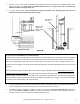
3. Installation of Pump – All Models
1. Removal of Old Pump:
Disconnect pump from power source before handling.
Separate the discharge pipe at either the check valve or at the union. If neither a check valve nor a union is part
of the existing discharge pipe, cut the pipe with a hacksaw and remove the pump (A union or check valve will
need to be installed at this cut).
2. Set the new pump in place making sure the float switch has adequate clearance and will not hang-up on the pit
wall. The float must be free to move throughout its travel and not contacting the pump body, piping, or other
objects.
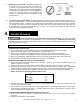
3. Depending on the model, either a 1-1/4” or 1-1/2” threaded discharge is provided on the pump for connection to
the discharge pipe (See Figure A for the discharge size of your specific model). Do not reduce the discharge size
to less than 1-1/4”, as this will affect pump flow and performance. Schedule 40 PVC pipe is recommended;
however, flexible discharge hose kits may be used for temporary installations.
4. Connect the pipe or the discharge hose to the discharge of the pump. HAND TIGHTEN ONLY. Overtightening
may cause the pump housing to crack.
Figure A.
MODEL DISCHARGE SIZE
101 1-1/4”
230-Series 1-1/2”
240-Series 1-1/2”
450-Series 1-1/2”
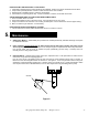
*NOTE: Pedestal pump model 101 requires assembly of the float, rod and guide. Snap the plastic guide into
position with its pin located in the center hole on the column of the pump. Insert the threaded end of the float
rod down through the hole in the guide and attach the float ball to the threaded end. Remove the upper rubber
stop and insert the rod through the hole in the switch arm. Replace the upper rubber stop at least ½” from the
end of the rod.