CONTROL PANEL INSTALLATION INSTRUCTIONS Single Phase Duplex Page 2-7 3-Phase Duplex Page 8-13
Single Phase Duplex AE21L=3, AE21H=3, AE21L=4, AE21H=4 AE24L=3, AE24H=3, AE24L=4, and AE24H=4 Manufactured by SJE-Rhombus® Installation Instructions and Operation/Troubleshooting Manual 7000 Apple Tree Avenue Bergen, New York 14416 Phone: 1-800-543-2550 Email: liberty@libertypumps.com www.libertypumps.com This control panel must be installed and serviced by a licensed electrician in accordance with the National Electric Code NFPA-70, state and local electrical codes.
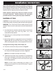
Installation Instructions Most single phase duplex panels are designed to operate as three or four float systems. The three float system is standard performing the common pump stop, lead pump start, and lag pump start/high level alarm functions. The four float system utilizes separate floats for lag pump start and high level alarm. FIGURE 1: Three float duplex NOTE: Options ordered may affect the number of floats and their functions.
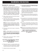
Installation Instructions Mounting the control panel 1. Determine mounting location for panel. If distance exceeds the length of either the float switch cables or the pump power cables, splicing will be required. For outdoor or wet installation, we recommend the use of a SJE-Rhombus® liquid-tight junction box with liquid-tight connectors to make required connections. You must use conduit sealant to prevent moisture or gases from entering the panel. 2.
Operations Control and Alarm Lights Single phase duplex panels are designed to operate with three or four floats for pump sequencing. The standard float functions are common pump stop, lead pump start, lag pump start/alarm (three floats), or separate lag and alarm floats (four floats). Three Float Operation: As the liquid level rises to the stop float and tips it to the ON (closed) position, the panel will remain inactive. As the liquid level tips the lead float, the lead pump will start.
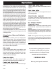
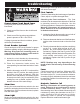
Troubleshooting the alarm light. If the light does not activate, replace with bulb of same type. Float Controls Check the floats during their entire range of operation. Clean, adjust, or replace damaged floats. Checking the float resistance - The float resistance can be measured to determine if the float is operating correctly or is defective. Use the following procedure to measure the float resistance. Warning: Disconnect all incoming power to panel.
Liberty Pumps Two-Year Limited Warranty *NOTE: Liberty Pumps, Inc. assumes no responsibility for damage or injury due to disassembly in the field. Disassembly, other than at Liberty Pumps or its authorized service centers, automatically voids warranty. Liberty Pumps, Inc. warrants that pumps of its manufacture are free from all factory defects in material and workmanship for a period of 2 years from the date of purchase.
Three Phase Duplex AE34=3-131, AE34=3-141, AE34=3-171, AE34=3-191, AE34=3-511, AE34=4-131, AE34=4-141, AE34=4-171, AE34=4-191, AE34=5-511, AE54=3-121, and AE54=4-121 Manufactured by SJE-Rhombus® Installation Instructions and Operation/Troubleshooting Manual 7000 Apple Tree Avenue Bergen, New York 14416 Phone: 1-800-543-2550 Email: liberty@libertypumps.com www.libertypumps.
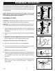
Installation Instructions FIGURE 1: Three float duplex Most three phase duplex panels are designed to operate with three or four float systems. The three float system is standard, performing the common pump stop, lead pump start, and lag pump start/high level alarm functions. The four float system utilizes separate floats for each function. NOTE: Options ordered may affect the number of floats and their functions. Please reference the schematic provided with the control panel for proper installation.
Installation Instructions Mounting the Control Panel 1. Determine mounting location for panel. If distance exceeds the length of either the float switch cables or the pump power cables, splicing will be required. For outdoor or wet installation, we recommend the use of an SJE-Rhombus® liquid-tight junction box with liquid-tight connectors to make required connections. You must use conduit sealant to prevent moisture or gases from entering the panel. 2. Mount control panel with mounting devices furnished. 3.
Operations trip, the magnetic contactor will be disabled. In the event of an overload trip, the motor protective switch must be reset by first turning the selector handle counterclockwise to the OFF position and then turning the handle 90o clockwise to the ON position. Three phase duplex panels are designed to operate with three or four floats for pump sequencing.
Troubleshooting resistance). Replace the float if you do not get this reading. With the float in the ON position, the scale should read nearly zero (very low resistance). Replace the float if you do not get this reading. NOTE: Readings may vary depending on the length of wire and accuracy of the measuring device. Alarm Horn Fuses Pressing the alarm test/normal/silence switch to the test position or activating the alarm float should turn on the alarm horn.
Liberty Pumps Two-Year Limited Warranty *NOTE: Liberty Pumps, Inc. assumes no responsibility for damage or injury due to disassembly in the field. Disassembly, other than at Liberty Pumps or its authorized service centers, automatically voids warranty. Liberty Pumps, Inc. warrants that pumps of its manufacture are free from all factory defects in material and workmanship for a period of 2 years from the date of purchase.