
Install Instructions
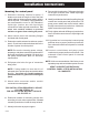
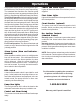
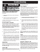


Table Of Contents

Operations
Three phase duplex panels are designed to operate
with three or four floats for pump sequencing. The
standard float functions are common pump stop, lead
pump start, lag pump start/alarm (three floats), or
separate lag and alarm floats (four floats). Other float
options, such as redundant off, are available.
Three Float Operation: As the liquid level passes
the stop float and tips it to the ON (closed) position,
the panel will remain inactive. As the liquid level tips
the lead float, the lead pump will start. If the liquid
level tips the lag/alarm float, the lag pump will start
and the audio/visual alarm will activate. Both pumps
and the alarm will remain active until the liquid level
drops and the lag float is in the OFF (open) position.
At this time the alarm will silence. Both pumps will
remain on until the liquid level drops to normal and
all three floats are in the OFF (open) position. When
both pumps have stopped running, the alternator will
switch the lead pump and lag pump operating
functions in the next sequence.
Four Float Operation: The alarm will activate and
remain on only if the alarm float is tipped to the ON
(closed) position.
Alarm System (Horn and Indicator)
When an alarm condition occurs, a red light and a
horn will be activated. If the test/normal/silence switch
is moved to the silence position, the horn will be
silenced. When the alarm condition is cleared, the
alarm system is reset. The alarm system can be
tested by moving the test/normal/silence switch to
the test position.
Control/Alarm Switch
Allows the control/alarm power to be turned on or
off.
HOA Switch
A hand-off-automatic switch is provided for each
pump. In the hand mode, the pump will turn on unless
other safety features are employed. In the automatic
mode, the pump will turn on from commands by the
float switches.
Motor Protective Switch
A motor protective switch is supplied for each pump
to provide an adjustable overload, branch circuit
protection and disconnect. The overload must be
set in the field. To set the overload, dial the amp scale
to the pump’s full load amp rating (FLA). If the FLA’s
are unknown, use a calibrated amp meter to
measure the pump amperage draw under loaded
conditions. An auxiliary contact is wired in series with
the magnetic contactor coil so that on an overload
trip, the magnetic contactor will be disabled. In the
event of an overload trip, the motor protective switch
must be reset by first turning the selector handle
counterclockwise to the OFF position and then
turning the handle 90
o
clockwise to the ON position.
Control/Alarm Light
The light will illuminate when the control ON/OFF
switch is in the ON position.
Pump Run Lights
Each pump has a run light. The run light will be ON in
either the hand or the automatic mode when the
pump is called to run.
Float Status Lights
Lights will illuminate when the respective float is in
the closed position.
Dry Auxiliary Contacts (optional)
Normally open - Contacts are open under normal
conditions and closed when alarm condition is
present.
Normally closed - Contacts are closed under
normal conditions and open when alarm condition
is present.
Both types automatically reset once alarm condition
is cleared.
Seal Failure Circuit and Indicator Light
(optional)
The seal fail circuit has resistance sensitivity and
will sense the presence of water in the pump seal
chamber. Upon installation, turn the sensitivity dial
on the seal fail module to the point where the light
turns on, then dial back slowly until the light turns off.
If water enters the seal chamber at this point, the
seal fail circuit will sense the change in resistance.
After a short time delay, the indicator light will turn
on. When the condition is cleared, the relay will de-
energize and the indicator light will turn off. The seal
fail relay has a sensitivity adjustment so that false
readings may be tuned out.
Thermal Cutout (optional)
The thermal cutout is wired in series with the
magnetic contactor coil. If the pump’s thermal switch
opens on high temperature, the contactor will turn
off and stop the pump. When the thermal switch
cools and closes, the magnetic contactor will turn on
if the pump is called to run.
NOTE: Some options ordered may not be included
in this manual.
- 4 -
7228000A