
Install Instructions

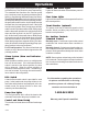
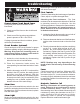
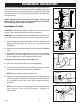
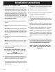
Table Of Contents

Most single phase duplex panels are designed to operate as
three or four float systems. The three float system is standard
performing the common pump stop, lead pump start, and lag
pump start/high level alarm functions. The four float system utilizes
separate floats for lag pump start and high level alarm.
NOTE: Options ordered may affect the number of floats
and their functions. Please reference the schematic
provided with the control panel for proper installation.
Installation of Floats
CAUTION: If control switch cables are not wired and mounted
in the correct location, the pump system will not function properly.
WARNING: Turn off all power before installing floats in pump
chamber. Failure to do so could result in serious or fatal electrical
shock.
1. Use float label kit to identify and label cables on both float
and stripped ends (stop, lead, lag, alarm, etc.). See
schematic for float options.
2. Determine your normal operating level, as illustrated in
Figures 1-2.
3. Mount float switches at appropriate levels as illustrated in
Figures 3-5. Be sure that floats have free range of motion
without touching each other, or other equipment in the basin.
If using the mounting clamp; follow steps 4-6.
4. Place the cord into the clamp as shown in Figure 5.
5. Locate the clamp at the desired activation level and secure
the clamp to the discharge pipe as shown in Figure 5.
NOTE: Do not install cord under hose clamp.
6. Tighten the hose clamp using a screwdriver. Over tightening
may result in damage to the plastic clamp. Make sure the
float cable is not allowed to touch the excess hose clamp
band during operation.
NOTE: All hose clamp components are made of 18-8
stainless steel material. See your SJE-Rhombus
®
supplier
for replacements.
FIGURE 1: Three float duplex
FIGURE 5: Mounting clamp detail
FIGURE 4: Float with cable weight
FIGURE 3: Internally weighted float
FIGURE 2: Four float duplex
Installation Instructions
7249000A
- 2 -