
Installation Sheet


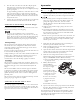


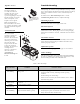
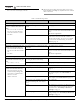


Table Of Contents

12 | EN Copyright © Liberty Pumps, Inc. 2020
All rights reserved. 5755000K
Impeller Access
Once the bottom of the
motorized cartridge is
accessible, the fasteners
retaining the volute can be
removed and the volute
separated by pulling it away. The
impeller chamber can now be
cleaned if required, or the
impeller can be replaced.
Note: the impeller has a
left-handed thread. To remove,
use a slotted screwdriver to hold
the shaft and turn the impeller
clockwise.
Control Switch
The control switch
cartridge is mounted to
the main cover with
fasteners. The control has
two power cords; first is
the main power cord that
plugs into the GFCI
receptacle and the other
powers the motorized
cartridge. The motorized
cartridge must be
removed to disconnect
this cord. Refer to
Accessibility to
Motorized Cartridge for
details.
Troubleshooting
Liberty Pumps, Inc. assumes no responsibility for damage or injury
due to disassembly in the field. Disassembly, other than at Liberty
Pumps or its authorized service centers, automatically voids
warranty.
In addition to the Alarm Panel Help in Table 1 and the
Troubleshooting Matrix in Table 2, verify the following:
Plumbing System
Flush toilet and ensure water supply is turned on.
Electrical System
Ensure breaker and receptacle GFCI are on. Check condition of
circuit breaker or fuse. Ensure plug is not loose. If the pumping
unit thermal overload has activated, it will take about 20 minutes
to reset.
Decorative Covers
Ensure decorative covers are installed and fully seated such that
safety switch is activated. The green LED is solid when safety
switch is properly activated.
Hydraulic System
Check that the discharge pipe and vent pipe are not blocked.
Water Leakage
If the macerating pump turns on intermittently without flushing
the toilet or collecting water drainage from sink, shower, or tub,
check for leakage from the toilet tank flush valve.
Impeller has
a left-handed thread
(counterclockwise to
tighten)
Table 1. Alarm Panel Help
Label
LED Color/State
Condition Corrective Action
ALARM
Red/Blinking
Water is not being evacuated from
holding tank.
1. Verify unit is plugged into outlet.
2. Verify Green LED is steady, indicating normal operating
condition.
3. Check discharge line for blockage.
4. If items 1-3 do not remedy the alarm condition, refer to Table 2
Troubleshooting Matrix.
LOW BATTERY
Yellow/Steady
Battery is missing, defective, or needs to
be replaced.
1. Replace with new battery.
POWER
Green/Steady
Normal operating condition.
POWER
Green/Blinking
Safety switch condition (no signal from
safety switch; unit will not operate).
1. Verify decorative covers in place.
2. Verify magnet in place on underside of decorative cover.
3. Safety switch is broken; consult factory.