
Manual

©SJE-Rhombus
Printed in USA
1031286D • Rev 06/12
7281000A
Warranty void if panel is modifi ed.
Call factory with servicing questions:
1-800-543-2550
This control panel must be installed and serviced by a
licensed electrician in accordance with the National Electric Code
NFPA-70, state and local electrical codes. All conduit running from
the sump or tank to the control panel must be sealed with conduit
sealant to prevent moisture or gases from entering the panel. NEMA
4X enclosures are for indoor or outdoor use, primarily to provide
a degree of protection against corrosion, windblown dust and rain,
splashing water and hose-directed water. Cable connectors must be
liquid-tight in NEMA 4X enclosures.
The Level Sensor is suitable for use in sewage applications.
Do NOT use in potable water.
Intelligent Panel Series control panels are designed to control pump(s).
The controller records pump status, number of cycles, elapsed run
time, alarm counts, and signal error counts.
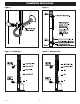
Mounting the Control Panel
Note: The control panel should not be mounted in a location that may
be subject to submersion.
1. Determine mounting location for panel. If distance exceeds the
length of either the sensor or fl oat cables or the pump power
cables, splicing will be required. Note: For splicing Level Sensor
cord, use only shielded cable. Splice conductors as well as
shielding. Maximum total cable length is 100 feet. For outdoor
or wet installation, we recommend the use of an SJE-Rhombus
®
liquid-tight junction box with liquid-tight connectors to make required
connections. You must use conduit sealant to prevent moisture
or gases from entering the panel.
2. Mount control panel with mounting devices furnished.
3. Determine conduit entrance locations on control panel. Check local
codes and schematic for the number of power circuits required.
(Level Sensor cable requires separate conduit from power
and pump cables.)
Note: Be sure the proper power supply voltage, amperage, and phase
meet the requirements of the pump motor(s) being installed. If in doubt,
see the pump identifi cation plate for voltage/phase requirements.
4. Drill proper size holes for type of connectors being used.
Note: If using conduit, be sure that it is of adequate size to pull the
pump cable(s) through.
5. Attach cable connectors and/or conduit connectors to control panel.
FOR INSTALLATION REQUIRING A SPLICE, FOLLOW STEPS 6-10;
FOR INSTALLATION WITHOUT A SPLICE, GO TO STEP 11.
6. Determine location for mounting junction box according to local
code requirements. Do not mount the junction box inside the
sump or basin.
Intelligent Panel Series
Installation Instructions and Operation/Troubleshooting Manual
Installation
7000 Apple Tree Avenue
Bergen, New York 14416 USA
Phone: 1-800-543-2550
www.libertypumps.com