
Use and Care Manual


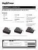


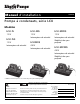

Table Of Contents

7196000G Copyright © Liberty Pumps, Inc. 2020
All rights reserved. 3 | EN
Do not modify the pump/pump system in any way.
Modifications may affect seals, change the electrical loading
of the pump, or damage the pump and its components.
All pump/pump system installations shall be in compliance
with all applicable Federal, State, and Local codes and
ordinances.
Do not allow children to play with the pump.
Do not allow any person who is unqualified to have contact
with this pump system. Any person who is unaware of the
dangers of this pump system, or has not read this manual,
can easily be injured by the pump system.
Do not remove any tags or labels from the pump or its cord.
Do not use this product with flammable, explosive, or
corrosive fluids. Do not use in a flammable and/or explosive
atmosphere as serious injury or death could result.
This product contains chemicals known to the State of
California to cause cancer and birth defects or other
reproductive harm. www.p65warnings.ca.gov.
This pump has been evaluated for use with water only.
Do not dispose of materials such as paint thinner or other
chemicals down drains. Doing so could chemically attack and
damage pump system components and cause product
malfunction or failure.
Do not use pumps with fluid over 150°F (65°C). Operating the
pump in fluid above this temperature can overheat the pump,
resulting in pump failure.
Do not use pump system with mud, sand, cement,
hydrocarbons, grease, or chemicals. Pump and system
components can be damaged from these items causing
product malfunction or failure. Additionally, flooding can
occur if these items jam the impeller or piping.
Do not allow pump to freeze.
Pump Installation
A. Select a location that is level and below the condensate pan
drain. The unit may be mounted on a wall by using the
mounting tabs on the tank, which are 10-9/16” apart. A
condensate neutralizer may be required by some codes to
keep condensate pH in an acceptable range for discharge
into drains.
B. Connect the drain pan to one of the 3 intake holes. Use vinyl
tubing, PVC, or any other suitable material. Be sure the tubing
or pipe extends into the inlet of the tank by at least 1". The
discharge connection to the check valve may be made with
3/8” vinyl tubing secured by a hose clamp (not included), or
the barb may be removed by sawing so that threaded fittings
may be attached. The thread is 1/4” NPT. Connect the pipe or
the discharge hose to the discharge of the pump.
Hand-tighten Only. Over-tightening may cause the pump
housing to crack. Once the discharge tubing has been
extended to the required height it should be slanted
downward, if possible, to assist in drainage. Note: For best
results, do not extend discharge tubing beyond 12' vertically
for the LCU-15 and 17' for the LCU-20S, LCU220S, LCU-SP20S,
or LCU-SP220S.
C. The safety switch leads (all models except LCU-15) should be
connected to a Class 2 low voltage circuit (not to exceed
30 volts). Using this feature may prevent damage from
condensation overflowing if the discharge becomes blocked
or if the pump fails. The leads may be connected in series
with the low voltage thermostat circuit so as to shut down the
heating/air-conditioning system if the water level in the pump
tank rises beyond normal, or they may be connected to an
external alarm.
D. To provide maximum mounting positions, the tank cover may
be removed and rotated 180° so that the check valve will be
on the opposite side of the unit. To remove the lid from the
tank, insert a screwdriver in the slot and pry the tank outward,
while lifting the lid. After removing and rotating, be sure the
lid snaps back into place firmly.
E. When all mounting and water connections are secure,
connect the unit to an electrical supply.
Disconnect electrical power at fuse or circuit breaker box
before making any connections.
The power cord must be connected to a constant source of
power (not a fan or other device that runs intermittently)
matching the voltage specified on the pump nameplate.
If connecting a pump with a stripped wire cord end, power
connections must be made within a junction box or
appropriate enclosure and must comply with the NEC and
any applicable codes. Wiring is as follows: GREEN is ground,
BLACK is line, and WHITE is neutral (115V) or line2 (230V).
F. To ensure proper installation, energize power and test the
unit by adding water to the tank until the pump activates. Be
sure the water discharges properly. Finally, check the
connections for leakage and proper discharge pipe routing.
Maintenance and Troubleshooting
Accidental contact with electrically live parts, items, fluid, or
water can cause serious injury or death.
Always disconnect the pump from power source before
attempting to service the pump. Fatal electrical shock could
occur.
Maintenance
Periodically inspect the condensate pump tank to ensure it is free
of accumulated dirt or sludge. Do not use solvent cleaners. Clean
tank with mild soap and warm water only. Clean inlet and outlet
piping. Reassemble system and check for correct operation.
Pour enough water into the tank to activate the pump periodically
when not normally in use.
RISK OF SERIOUS INJURY OR DEATH
RISK OF ELECTRIC SHOCK