
Install Instructions


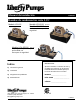


Table Of Contents

1
General Information – All Models
Before installation, read the following instructions carefully. Closely following these instructions will eliminate
potential operating problems, assuring years of trouble-free service.
Risk of electric shock. The pump is supplied with a grounding conductor and grounding-
type attachment plug. To reduce the risk of electric shock, be certain that it is connected only to a properly
grounded, grounding-type receptacle. Always disconnect the pump from the power source before handling
or making adjustments. Always wear rubber boots when servicing in wet areas. Make sure the pump
power source is a separately fused, grounded 3-wire type receptacle of 15-amp capacity. DO NOT
REMOVE GROUND PRONG OR PLUG. DO NOT USE AN EXTENSION CORD. Check to make sure
installation is in accordance with the National Electric Code and all applicable local codes. Installation and
servicing are to be conducted by qualified personnel.
DO NOT pump flammable liquids
DO NOT use around explosive materials
DO NOT handle unit with wet hands or while standing in water
DO NOT connect to any voltage other than that listed on the nameplate
DO NOT use in water over 150°F.
DO NOT modify the pump in any way
DO NOT expose pump or discharge to freezing temperatures
2
Installation of the Pump
A. Select a location that is level and below the condensate pan drain. The unit may be mounted on a wall by
using the mounting tabs on the tank, which are 10-9/16” apart. A condensate neutralizer may be required
by some codes to keep condensate pH in an acceptable range for discharge into drains.
B. Connect the drain pan to one of the 3 intake holes. Use vinyl tubing, PVC, or any other suitable material.
Be sure the tubing or pipe extends into the inlet of the tank by at least 1". The discharge connection to the
check valve may be made with 3/8” vinyl tubing secured by a hose clamp (not included), or the barb may
be removed by sawing so that threaded fittings may be attached. The thread is ¼” NPT. Connect the pipe
or the discharge hose to the discharge of the pump. HAND-TIGHTEN ONLY. Over-tightening may cause
the pump housing to crack. Once the discharge tubing has been extended to the required height it should
be slanted downward, if possible, to assist in drainage.
NOTE: For best results, do not extend
discharge tubing beyond 12' vertically for the LCU-15 and 17' for the LCU-20S, LCU220S,
or LCU-SP20S (Refer to performance chart).
C. The safety switch leads (all Models except LCU-15) should be connected to a class 2 low voltage circuit
(not to exceed 30 volts). Using this feature may prevent damage from condensation overflowing if the
discharge becomes blocked or if the pump fails. The leads may be connected in series with the low voltage
thermostat circuit so as to shut down the heating/air-conditioning system if the water level in the pump tank
rises beyond normal, or they may be connected to an external alarm.
D. To provide maximum mounting positions the tank cover may be removed and rotated 180° so that the
check valve will be on the opposite side of the unit. To remove the lid from the tank, insert a screwdriver in
the slot and pry the tank outward, while lifting the lid. After removing and rotating, be sure the lid snaps
back into place firmly.
7196000C
2