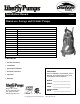
Installation Manual 5647000I Omnivore® Sewage and Grinder Pumps Models: LSG202A LSG202M LSG202M-C LSG203M LSG204M LSG205M 2 hp, 208/230V, 1 phase, Automatic 2 hp, 208/230V, 1 phase, Manual 2 hp, 208/230V, 1 phase, Manual, external caps 2 hp, 208/230V, 3 phase, Manual 2 hp, 440-480V, 3 phase, Manual 2 hp, 575V, 3 phase, Manual LSGX202A LSGX202M LSGX202M-C LSGX203M LSGX204M LSGX205M 2 hp, 2-Stage, 208-230V, 1 phase, Automatic 2 hp, 2-Stage, 208-230V, 1 phase, Manual 2 hp, 2-Stage, 208-230V, 1 phase, Man
Table of Contents SECTION 1 GENERAL INFORMATION------------------------------------------------------------------------------ 3 SECTION 2 INTRODUCTION-------------------------------------------------------------------------------------------- 4 SECTION 3 MECHANICAL INSTALLATION ----------------------------------------------------------------------- 4-6 SECTION 4 ELECTRICAL CONNECTION-------------------------------------------------------------------------- 6-8 SECTION 5 OPERATION -------------
1. General Information Before installation, read the following instructions carefully. Each Liberty pump is individually factory tested to insure proper performance. Closely following these instructions will eliminate potential operating problems, assuring years of trouble-free service. Risk of electric shock. Always disconnect the pump from the power source before handling or making adjustments.
2. 2-1 Introduction INTRODUCTION This manual was prepared to assist you in the correct installation, operation, and maintenance of your Liberty pump. Please read it completely before installing the pump. Make certain that you are familiar with the contents, and the chapters on installation and operation are fully understood before running the pump. Liberty Pumps are designed for minimal maintenance. greater operating reliability.
3-2 STORAGE BEFORE USE Liberty pumps are shipped from the factory ready for installation and use. They should be held in storage if the pump station is not complete. If storage is necessary, the pump should remain in its shipping container. It should be stored in a warehouse or storage shed that has a clean, dry temperature-stable area where the pump and its container should be covered to protect it from water, dirt, dust, etc. The ends of the cables - (plugs) must be protected against moisture.
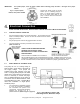
IMPORTANT: For 3-phase pumps, check for proper rotation before installing pump into basin. See figure A for proper rotation. Check three phase pumps for proper rotation prior to installing pump(s) in basin. To change rotation, reverse any two of the three power leads to the pump. Code the wires for reconnection after installation. Fig. A – Proper impeller rotation, three phase models Bottom View 4. Electrical Connection AFTER THE PUMP IS INSTALLED, THE ELECTRICAL CHECKS OF SECTION 4 MUST BE PERFORMED.
4-3 CONTROL PANEL OPERATION REFER TO WIRING DIAGRAM INCLUDED WITH CONTROL PANEL. IF THERE IS NO WIRING DIAGRAM, CONTACT THE MANUFACTURER TO OBTAIN ONE. DO NOT ATTEMPT TO CONNECT PUMP WITHOUT A WIRING DIAGRAM. 4-4 EXTERNAL CAPACITORS The LSG202M-C and LSGX202M-C (208-230V SINGLE PHASE UNITS) are designed such that the capacitors and start relay are mounted in a control panel external from the pump. The most basic wiring diagram is illustrated in Figure C.
4-6.1 FLOAT SEQUENCE- PIGGY BACK 2. The pump runs until the liquid level falls below the “PUMP OFF” level of the float (Factory set at 7" minimum), emptying the wet well. 4-6.2 FLOAT SEQUENCE- SIMPLEX 1. As the liquid level in the wet well rises, the “PUMP OFF” float tilts, closing the switch (This level must be set at a minimum of 7"). As the liquid level continues to rise, the “PUMP ON” float tilts. This switch closes, starting the pump. 2.
5. 5-1 Operation OPERATION After the electrical and mechanical installations have been performed, the pump is ready for operation. No operational procedures are required except to apply rated power to the pump. There are no specific shutdown procedures beyond disconnecting the power supply. IF THE ROTATION OF A SINGLE PHASE PUMP IS INCORRECT, NOTIFY THE LIBERTY PRODUCT SERVICE DEPARTMENT IMMEDIATELY. DO NOT SWITCH THE POWER SUPPLY LEADS. DO NOT OPERATE THE PUMP.
TROUBLESHOOTING CHART: LSG200 SYMPTOM 1. PUMP WILL NOT START POSSIBLE CAUSE ACTION A. Power supply failure A. Check power supply Check out electrical system for loose connections Check operating voltage B. Burned out fuse or tripped circuit B. Check circuit protectors breaker C. Damaged power cable C. Check external cable for damage – repair D. Jammed impeller D. Inspect and remove jamming object 2. REPEATED TRIPPING E. Water inside motor E. Refer to Symptom 5 and 6 A.
FIGURE 2 CONTROL PANEL INSTALLATION ©Copyright 2012 Liberty Pumps Inc.
FIGURE 3 TYPICAL INSTALLATION WITHOUT GUIDE RAIL ©Copyright 2012 Liberty Pumps Inc.
PERFORMANCE CURVE Omnivore Grinders 0 5 10 15 20 25 30 35 40 45 50 55 200 86.6 190 82.3 In order to ensure sufficient fluid velocity to carry solids, (generally accepted to be 2 feet per second) 180 170 73.6 1-1/4" PIPE 160 77.9 1-1/2" PIPE 150 Maximum Total Dynamic Head is dependent on friction factors of the piping system. Consult factory for proper pump sizing. 69.3 64.9 1-800-543-2550 140 130 60.6 56.3 2" PIPE 51.9 110 47.6 LSGX-SERIES 100 43.3 90 39.0 80 34.
6. 3 Year Limited Warranty Liberty Pumps, Inc. warrants that pumps of its manufacture are free from all factory defects in material and workmanship for a period of 3 years from the date of purchase. The date of purchase shall be determined by a dated sales receipt noting the model and serial number of the pump. The dated sales receipt must accompany the returned pump if the date of return is more than 3 years from the "CODE" (date of manufacture) number noted on the pump nameplate.
Manuel d’installation 5647000I Pompes omnivores de relèvement des eaux usées et broyeuses Modèles : LSG202A LSG202M LSG202M-C LSG203M LSG204M LSG205M 2 hp, 208/230 V, monophasée, automatique 2 hp, 208/230 V, monophasée, manuelle 2 hp, 208/230 V, monophasée, manuelle, condensateur externe 2 hp, 208/230 V, triphasée, manuelle 2 hp, 440-480V, triphasée, manuelle 2 hp, 575V, triphasée, manuelle LSGX202A LSGX202M LSGX202M-C 2 hp, 2 positions, 208-230 V, monophasée, automatique 2 hp, 2 positions, 208-230 V ,
Table des matières SECTION 1 RENSEIGNEMENTS GÉNÉRAUX ------------------------------------------------------------------- 3 SECTION 2 INTRODUCTION--------------------------------------------------------------------------------------------4 SECTION 3 INSTALLATION MÉCANIQUE ------------------------------------------------------------------------ 4-6 SECTION 4 RACCORDEMENT ÉLECTRIQUE -------------------------------------------------------------------- 6-8 SECTION 5 FONCTIONNEMENT -----------------
1. Renseignements généraux Lire attentivement les directives avant d’effectuer l’installation. Chaque pompe de marque Liberty est testée individuellement en usine pour assurer son bon fonctionnement. Le fait de suivre ces directives à la lettre éliminera les risques de dysfonctionnement et assurera des années de fonctionnement sans soucis. Danger d’électrocution.
2. 2-1 Introduction INTRODUCTION Ce manuel est destiné fournir les renseignements nécessaires à l’installation, l’utilisation et l’entretien de la pompe Liberty. Il est recommandé de lire entièrement les directives avant d'installer la pompe. S’assurer d’être familier avec le contenu et de bien comprendre les chapitres relatifs à l’installation et l’utilisation de la pompe avant de la faire fonctionner. Les pompes Liberty sont conçues pour ne nécessiter qu’un entretien minimal.
3-2 ENTREPOSAGE AVANT UTILISATION Les pompes Liberty sont expédiées de l’usine prêtes à être installées et utilisées. Elles devraient être entreposées si la station de pompage n’est pas complète. S'il est nécessaire d'entreposer la pompe, celle-ci devrait demeurer dans son contenant d'expédition. Elle devrait être conservée dans un entrepôt ou une remise, dans un endroit propre et sec dont la température est stable.
4. Raccordement électrique UNE FOIS LA POMPE INSTALLÉE, IL FAUT EFFECTUER LES VÉRIFICATIONS ÉLECTRIQUES DE LA SECTION 4. 4-1 FONCTIONNEMENT DE L’INTERRUPTEUR SIAMOIS 1. Brancher l’interrupteur siamois dans une prise 6-20R. La prise doit être reliée à un disjoncteur d'une intensité de 30 ampères. S’assurer que le disjoncteur est éteint avant d'y brancher l'interrupteur. 2. Brancher le cordon d’alimentation électrique de la pompe dans l’interrupteur siamois tel qu'illustré. 3.
1. La pompe peut fonctionner avec une tension de 230 V ou de 208 V. S'assurer que la tension de l'alimentation est la même. Les pompes sont fournies avec des fiches de cordons de 6-20P (20 ampères). La plupart du temps, la pompe sera branchée dans une prise. S’il est nécessaire de brancher la pompe dans un panneau, il faut alors retirer la fiche et dénuder les bornes.
4-5.1 1. SÉQUENCE DU FLOTTEUR – SIAMOIS (MODÈLE AUTOMATIQUE LSG202A ET LSGX202A) À mesure que le niveau de liquide monte dans la bâche d’aspiration, le flotteur bascule et ferme l’interrupteur. Cela fait démarrer la pompe. 2. La pompe tourne jusqu’à ce que le niveau de liquide descende en-dessous du niveau « POMPE ARRÊTÉE » du flotteur (établi à au moins 17,8 cm [7 po] en usine), vidant la bâche d'aspiration. 4-5-2 SÉQUENCE DU FLOTTEUR – SIAMOIS (MODÈLE MANUEL) 1.
5. 5-1 Fonctionnement FONCTIONNEMENT Une fois les installations électriques et mécaniques complétées, la pompe est prête à fonctionner. Aucune procédure de fonctionnement n’est nécessaire sauf pour appliquer la puissance nominale à la pompe. Il n’y a pas de procédure de fermeture particulière au-delà du débranchement de l’alimentation électrique. SI LA ROTATION D’UNE POMPE UNIPOLAIRE EST INCORRECTE, EN AVISER IMMÉDIATEMENT LE SERVICE D’ENTRETIEN DES PRODUITS LIBERTY.
TABLEAU DE DÉPANNAGE : LSG200 SYMPTÔME 1. LA POMPE REFUSE DE CAUSE POSSIBLE ACTION A. Panne d’alimentation électrique A. Vérifier l’alimentation électrique Vérifier la présence de raccordements électriques desserrés Vérifier la tension de fonctionnement DÉMARRER B. Fusible brûlé ou disjoncteur sauté B. Vérifier C. Câble d’alimentation endommagé C. Vérifier le câble extérieur et les dispositifs protection des circuits de réparer au besoin D. Rotor coincé D.
FIGURE 2 INSTALLATION DU PANNEAU DE COMMANDE ©Copyright 2012 Liberty Pumps Inc.
FIGURE 3 INSTALLATION TYPE SANS RAIL DE GUIDAGE ©Copyright 2012 Liberty Pumps Inc.
PERFORMANCE CURVE COURBES DE RENDEMENT Omnivore Grinders Pompes omnivores broyeuses 0 5 10 15 20 25 30 35 40 45 50 55 200 86.6 190 180 170 TUYAU DEPIPE 1½ PO 1-1/2" 150 77.9 73.6 TUYAU DEPIPE 1¼ PO 1-1/4" 160 L'élévation Maximum Totaldynamique Dynamic Headmaximum dépend de facteurs de isacceptable dependent on friction factors friction de system. la tuyauterie. of the piping Consult Consulter factory for proper pump sizing. la taille le fabricant pour déterminer 69.3 64.
6. Garantie limitée de 3 ans Liberty Pumps, Inc. garantit que les pompes sortant de son usine sont exemptes de tout défaut de matériau et de fabrication pour une période de 3 ans à partir de la date d’achat. La date d'achat sera établie par une facture d’achat datée indiquant les numéros de modèle et de série de la pompe.
Manual de instalación 5647000I Bombas de Saneamiento y Trituradora Omnivore Modelos: LSG202A LSG202M LSG202M-C LSG203M LSG204M LSG205M LSGX202A LSGX202M LSGX202M-C LSGX203M LSGX204M LSGX205M 2 HP, 208/230V, monofásica, automática 2 HP, 208/230V, monofásica, manual 2 HP, 208/230V, monofásica, manual, condensador externo 2 HP, 208/230V, trifásica, manual 2 HP, 440-480V, trifásica, manual 2 HP, 575V, trifásica, manual 2 HP, 2 etapas, 208-230V, monofásica, automática 2 HP, 2 etapas, 208-230V, monofásica, ma
Contenido SECCIÓN 1 INFORMACIÓN GENERAL ------------------------------------------------------------------------------ 3 SECCIÓN 2 INTRODUCCIÓN ------------------------------------------------------------------------------------------- 4 SECCIÓN 3 INSTALACIÓN MECÁNICA ----------------------------------------------------------------------------- 4-6 SECCIÓN 4 CONEXIÓN ELÉCTRICA --------------------------------------------------------------------------------- 6-8 SECCIÓN 5 OPERACIÓN ------------
1. Información general Lea con atención estas instrucciones antes de instalar la bomba. Todas las bombas Liberty se someten a pruebas en fábrica para garantizar un funcionamiento adecuado. Siga estas instrucciones al pie de la letra para prevenir problemas de funcionamiento y asegurar años de servicio satisfactorio. Riesgo de descarga eléctrica. Desconecte la bomba siempre que vaya a moverla o a realizar algún ajuste.
2. 2-1 Introducción INTRODUCCIÓN El propósito de este manual es ayudarle a instalar, operar y mantener la bomba Liberty. Léalo totalmente antes de instalar el sistema. Antes de poner la bomba en funcionamiento, asegúrese de entender todo el contenido, incluidos los capítulos sobre instalación y operación. Las bombas Liberty requieren un mantenimiento mínimo. Sin embargo, para que duren el mayor tiempo posible y funcionen sin problemas es importante revisarlos con regularidad.
LA BOMBA NUNCA SE DEBERÁ ALMACENAR EN UN SUMIDERO INUNDADO SIN TERMINAR. SÓLO SE DEBERÁ COLOCAR EN EL SUMIDERO CUANDO SE PUEDA OPERAR CORRECTAMENTE. ALMACENAMIENTO A LARGO PLAZO Si hiciera falta almacenar la bomba durante un período prolongado, hágalo en un recinto cerrado limpio y seco a temperatura estable. Cubra la bomba para protegerla del polvo, la suciedad y el agua. También los enchufes se deberán proteger contra la humedad. 1. 2. No deje que la unidad se congele. 3.
4. Conexión eléctrica CUANDO HAYA INSTALADO LA BOMBA, COMPRUEBE LAS CONEXIONES ELÉCTRICAS COMO SE INDICA EN LA SECCIÓN 4. 4-1 OPERACIÓN DEL INTERRUPTOR EN CASCADA 1. Enchufe el interruptor en cascada en el tomacorriente 6-20R. El tomacorriente tiene que estar cableado a un disyuntor de 30 amperios. Apague el disyuntor antes de enchufar el interruptor. 2. Enchufe el cordón de alimentación eléctrica en el interruptor en cascada como se indica en la ilustración. 3.
1. La bomba funciona con una tensión nominal de 230V o 208V. Compruebe que ésta sea la tensión de alimentación. Las bombas vienen con enchufes de 6-20P (20 amp). En la mayoría de los casos la bomba irá enchufada en un tomacorriente. Si la bomba va a ir cableada a un panel, habrá que retirar el enchufe y pelar los hilos. La conexión de estos cables la tendrá que llevar a cabo un electricista calificado según la identificación de cada cable individual y las conexiones correspondientes en el panel de control.
2. La bomba seguirá funcionando hasta que el nivel de líquido caiga por debajo del nivel de apagado establecido (fijado en fábrica a un mínimo de 17.77 cm/7 plg.), con lo que se vaciará el sumidero. 4-5.2 SECUENCIA DEL FLOTADOR - SIMPLE (MODELOS MANUALES) 1. El flotador de apagado se va inclinando a medida que sube el nivel del sumidero inundado, con lo que cierra el interruptor. (El nivel debe estar a 17.77 cm/7 plg como mínimo).
COMPRUEBE SIEMPRE QUE NO HAYA CABLES SUELTOS Y OTRAS OBSTRUCCIONES QUE PUDIERAN CAUSAR LESIONES PERSONALES O DESPERFECTOS. 5-2 MANTENIMIENTO Y LUBRICACIÓN PERIÓDICOS Las bombas Liberty han sido diseñadas para ofrecer un servicio eficiente y confiable con un mínimo de mantenimiento preventivo. Estas tareas de mantenimiento son pocas pero muy importantes para asegurar años de servicio satisfactorio. Las revisiones se deben realizar a los intervalos recomendados.
DIAGNÓSTICO DE PROBLEMAS: LSG200 / LSGX200 PROBLEMA 1. LA BOMBA NO ARRANCA CAUSA POSIBLE ACCIÓN A. Fallo del suministro eléctrico A. Revise el suministro eléctrico Compruebe que no haya conexiones sueltas en el sistema eléctrico Compruebe la tensión de operación B. Se quemó un fusible o saltó el B. Compruebe los protectores de circuitos interruptor automático C. Cable de alimentación defectuoso C. Compruebe que no haya desperfectos en el cable externo. Repárelo 2. EL DISYUNTOR SALTA D.
FIGURA 2 INSTALACIÓN DEL PANEL DE CONTROL ©Copyright 2012 Liberty Pumps Inc.
FIGURA 3 INSTALACIÓN TÍPICA SIN GUIADERA ©Copyright 2012 Liberty Pumps Inc.
PERFORMANCE CURVE CURVA DE RENDIMIENTO Omnivore Grinders Bombas trituradoras Omnivore 0 5 10 15 20 25 30 35 40 45 50 55 200 86.6 190 82.3 order ensure sufficient fluid velocidad AInfin de to garantizar la suficiente del líquido para trasladar sólidos velocity to carry solids, (generally (la cual se acepta togeneralmente como de 60 cm accepted be 2 feet per second) por segundo) 180 170 77.9 73.6 TUBERÍA DE 1-1/4 PULG.
6. Garantía limitada de 3 años Liberty Pumps, Inc. garantiza que las bombas que fabrica están libres de defectos en los materiales y la mano de obra por un período de 3 años a partir de la fecha de compra. La fecha de compra se determinará con el recibo de compra fechado, que incluya el modelo y el número de serie de la bomba. Este recibo deberá acompañar a la bomba si la fecha de devolución ocurre más de 3 años después de la fecha de fabricación (código-CODE) indicada en la placa de la unidad.