
Install Instructions


©Copyright 2012 Liberty Pumps Inc. All rights reserved - 8 -
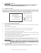
4-6.1 FLOAT SEQUENCE- PIGGY BACK (AUTOMATIC MODELS LSG202A & LSGX202A)
1. As the liquid level in the wet well rises, the float tilts, closing the switch. This starts the pump.
2. The pump runs until the liquid level falls below the “PUMP OFF” level of the float (Factory set at 7" minimum), emptying the
wet well.
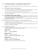
4-6.2 FLOAT SEQUENCE- SIMPLEX (MANUAL MODELS)
1. As the liquid level in the wet well rises, the “PUMP OFF” float tilts, closing the switch (This level must be set at a minimum of
7"). As the liquid level continues to rise, the “PUMP ON” float tilts. This switch closes, starting the pump.
2. The pump runs until the liquid level falls below the “PUMP OFF” float, emptying the wet well.
3. In the event of a malfunctioning float switch, control relay or pump, the liquid level rises and tilts the “HIGH LEVEL ALARM”
float. The alarm system will activate.
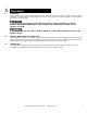
4-6.3 FLOAT SEQUENCE-DUPLEX (MANUAL MODELS)
1. As the liquid level in the wet well rises, the “PUMP OFF” tilts, closing the switch. As the liquid level continues to
rise, the “LEAD PUMP ON” float tilts. This switch closes, starting the lead pump. The pump runs until the liquid
level falls below the “PUMP OFF” float, emptying the wet well.
2. On the next rise of the liquid level, the other pump will start on the “LEAD PUMP ON” signal. The pumps will
continue to alternate their cycles.
NOTE: The ON/OFF float switch differential should be set as to not exceed 12 starts per hour.
3. If the liquid level rises to the “LAG PUMP ON" float, the second pump will start. Both pumps will run until the
liquid falls below the “PUMP OFF” float, emptying the wet well.
4. In the event of a malfunctioning float switch, control relay or pump, the liquid level rises and tilts the “HIGH LEVEL
ALARM” float. The alarm system will activate.
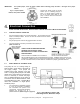
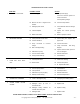
4-6.4 FLOAT SWITCH INSTALLATION
The engineering drawings will normally specify the levels for pump start and stop and high level alarm. If they are not
specified, these guidelines should be used to determine float switch locations.
PIGGY BACK SWITCH
(1-Float System)
Pump Off: Factory set. (Float tether 4")
Pump On: Factory set. (Float tether 4")
SIMPLEX PUMP STATION
(3-Float System)
Pump Off: Level to top of motor housing.
Pump On: Minimum 1-1/2 ft. above Pump Off Level.
High Level Alarm: Minimum 1 ft. above pump ON level. Below influent pipe.
DUPLEX PUMP STATION
(4-Float System)
Pump Off: Level to top of motor housing.
Lead Pump On: Minimum 1-1/2 ft. above Pump Off level.
Lag Pump On: Minimum 1 ft. above Lead Pump On level.
High Level Alarm: Minimum 1 ft. above Lag Pump On level. Below influent pipe.