
Install Instructions
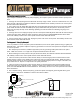

Installation of Preset Level Sensor Holder
Side Wall
Mount
Figure 5
Discharge Pipe
Mount
Page 3 of 6
Operation and Maintenance Manual
7000 Apple Tree Avenue, Bergen, NY 14416 Phone: (800) 543-2550-Fax: (585) 494-1839-www.libertypumps.com
Pump
Start
High Level
Probe
High Level
Float
5
1 2
3
4 6 7
Auxiliary Contacts
24VDC, 1A
Conect to Remote Alarm
Or BAS/SCADA System
Off
Probe
Start
Probe
Alarm
Probe
Float
Float
Circuit Board
Green
Yellow
Red
White
Black
5 Conductor Cable from
Preset Level Sensor
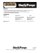
Figure 6
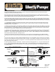
Figure 4
DWG#7235000G
Manual 7235000G
Off
Probe
Operation and Maintenance Manual
Operation and Maintenance Manual
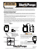
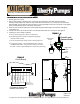
1. Review figures 4, 5 and 6.
2. Attach sensor holder to discharge pipe or separate pipe (mounted to side wall) using the stainless
steel pipe clamp. Make sure sensor is clear of inlet water and at least 1” to 2” away from any conductive
material. Make sure the bottom probe (off level) is at the same height as the top of the pump or just slightly
below ensuring submergence of the pump. See figure 5.
3. Route the five conductor cable to the control panel through the liquid tight cord connector and tighten
compression nut.
4. Connect the wires from the level sensor to the terminal strip inside the control panel. See figure 6.
5. If splicing on sensor cable is required:
A. For any splicing longer than 100 feet, consult factory.
B. Use liquid tight junction boxes and appropriate liquid tight
connectors and/or conduit.
C. Do not mix high and low voltage circuits in same junction box.
D. For level sensor splice, it is recommended to use 5 conductor,
18 AWG shielded cable. Only ground the shield on one end of
the cable – easiest to ground shield wire in panel to the ground
lug.
Preset Level
Sensor Holder