
Install Instructions
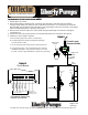
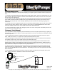

Mounting Hole (2)
Figure 8 - Mounting
Side Screw
120VAC Wallmount
Receptacle
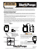
Figure 7 - Installing/Replacing Battery
Battery Strap
Connector
Duracell Model
MX1604B2
9 VDC Battery
Battery
Holder
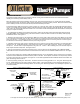
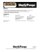
Figure 9 - Installing Field Wiring for
Auxiliary Contacts
Connects to BAS/SCADA system
Auxiliary Contacts
White - Common
Red - Normally Closed
Black - Normally Open
Class 2, 24 VDC/VAC(50/60HZ)
500 milliamps MAXIMUM!
Jam
Nut
2 wire cable
To BAS/SCADA
1/2" Strain
Relief
Use #8 X 1 1/4"
Self Tapping Screws
1/2" Electrical
Knockout
Center
Screw
Base
Base
Wire Nuts
Plastic
Cord
Holder
OilTector
Cover
Terminal Block
connects to terminal
blocks 6 & 7 of the
CONTROL PANEL
Figure 10
7000 Apple Tree Avenue, Bergen, NY 14416 Phone: (800) 543-2550-Fax: (585) 494-1839-www.libertypumps.com
Operation and Maintenance Manual
Page 4 of 6
DWG#7235000G
Manual 7235000G
The OilTector Remote Alarm Panel is powered by 120 VAC coming from standard wall outlets and is transformed to 9VDC.
Installing a 9 Volt battery provides battery back-up.
When the OilTector Control Panel’s Auxiliary Contacts “close” the buzzer and light will turn “on” and the alarm panel’s auxiliary
contacts will be activated. Pressing the “silence switch deactivates the buzzer and auxiliary contacts. When the OilTector Control
Panel’s Auxiliary Contacts reset, the remote alarm panel will automatically
reset itself.
Test product weekly. Make sure the green ”power on” light is “on”. Press the “Test” switch; the red alarm light and buzzer should
turn “on”. If the battery back up system is utilized, unplug the wall mount power supply (the green light will be off). Now press the
“Test” switch; the red alarm light and buzzer will turn “on”. If the buzzer sounds less loudly than when tested with the normal power
supply, then replace the battery.
1. To install/replace the battery for the backup power feature, remove the two side screws and
install 9 VDC battery (Duracell
model MX 1604B2). After installing battery, press the test button to activate the alarm to make sure the battery works properly.
Reinstall side screws. See Figures 7.
2. Determine mounting location for the Alarm Panel. Make sure power outlet is within 6 feet of the alarm. Make sure the outlet
is on a separate circuit breaker from any other device and not on a switched receptacle to maintain power integrity. Mount the
alarm using two #8 x 1 1/4" self tapping screws (not included). Use #8 plastic anchor if mounting to sheet rock. See Figure 8.
The alarm can be mounted up to 2500 feet from the panel using 18 ga wire.
3. If Auxiliary Contacts are used, continue; otherwise go to step 4. Remove cover from base and remove 1/2" electrical knockout
from base. Use 16 - 2 AWG stranded wire - make sure there is at least 6" of wire inside of enclosure. Install a 1/2" strain relief
with jam nut. Connect wires for required application using wire nuts. Caution
! - When installing wires, route all wires away from
sharp objects & internal components. See figures 9 & 10.
4. There are two terminals on the bottom of the alarm panel. Connect a wire from the first terminal to the CONTROL PANEL
terminal #6 and connect another wire from the second terminal of the alarm panel to CONTROL PANEL terminal #7. See Figure
8
5. Plug the power supply into a 120VAC, 50/60 HZ standard wall outlet. For UL applications, remove center screw on receptacle
and place cord from wallmount transformer inside the plastic cord holder. Secure plastic cord holder to
the receptacle by reinstall
ing screw to the center hole of receptacle. See Figure 8. For Canadian applications DO NOT INSTALL Plastic Cord Holder! The
green "Normal" light should come on.
6. Test the system by pressing the "Test" switch. The buzzer and the red warning light will be "on". The green "Normal" light will
be "off". While holding the “Test” switch, press the “Silence” switch. The buzzer will silence, but the alarm light will remain “on”.
Let go of the “Test” switch and the alarm light will turn “off” and the green “Normal” light will turn “On
” indicating the system is now
in a normal condition.
Operation and Maintenance Manual
Operation and Maintenance Manual
Operation and Maintenance Manual
Installation of the Alarm Panel