
Install Instructions

7000 Apple Tree Avenue Bergen, NY 14416 Phone: (800) 543-2550-Fax: (585) 494-1839-www.libertypumps.com
Operation and Maintenance Manual
P
age 5 of 6
DWG#7235000G
Manual 7235000G
:
Operation and Maintenance Manual
Operation and Maintenance Manual
Operation and Maintenance Manual
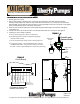
Testing the complete system
Upon complete installation of controls, pump and piping, the complete system should be tested for quality assur-
ance.
1. Test high oil circuit by lifting the float switch with the sump empty of water. Oil is non conductive like “air”, and
when the float is lifted only the HIGH OIL indicator will be illuminated. The auxiliary contacts in the control panel
and the remote alarm will activate.
2. Test a pump cycle by slowly filling tank with water. Stop filling tank with water when the level touches middle
probe. When the water touches the middle probe, pump should start and pump down to the bottom probe at
which time the pump will stop. Check discharge plumbing for leads and make sure discharge is going to the
correct area.
3. Test high water circuit. Unplug the pump from the control panel and slowly fill the tank until the water level just
touches the upper probe. When the water touches the upper probe, the HIGH WATER indicator will be illumi-
nated. The auxiliary contacts in the control panel and the remote alarm will activate.
4. Test the remote alarm for power loss. Unplug the power cord on the control panel. The auxiliary contacts will
close and the remote alarm will activate.
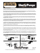
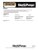
Testing panel - Using 5 gallon pail.
If it is not possible to test the complete system outlined above, then test the panel operation using a 5 gallon pail
filled with water. The system requires a temporary ground wire run from the control panel into the liquid in the pail
for correct operation.
1. Run Temporary Ground wire (14 AWG Copper Wire) from the ground lug inside panel and into the pail of
water. Make sure at least ½” of copper wire is exposed and immersed in the water.
2. Before lowering the sensor probe into the pail, lift the float switch, the HIGH OIL indicator will be illuminated.
The auxiliary contacts in the control panel and the remote alarm will activate.
3. Lower the sensor probe into the bucket of water slowly so that the longest probe is immersed in the water.
Slowly continue to lower so the middle probe touches the water, the pump should activate. While the pump is
activated, slowly remove the sensor probe out of the water until the longest probe is no longer in the water, the
pump should turn off. Repeat a couple of times for quality assurance.
4. Lower the sensor probe into the bucket of water slowly so that the longest probe and the middle probe are
immersed in water, the pump will activate. Continue to lower sensor probe so that water touches the shortest
probe, the HIGH WATER indicator will be illuminated. The auxiliary contacts in the control panel and the remote
alarm will activate.
5. This completes testing. Remove temporary ground from panel and retighten ground lug with all the green
wires. Return to manual for “Installation of Preset Level Sensor Holder”.
120 V
Receptacle
60500A0
Ground Lug
Temporary 14 AWG Ground Wire