
Install Instructions

©Copyright 2012 Liberty Pumps Inc. All rights reserved 9
Supplemental Installation Instructions
370XL/380XL Series 10’ stack test basins
XL Series sewage ejector basins are designed to withstand the 10’ stack test required by some municipalities. Proper
installation of the specified cover flange is essential to ensure that the test is met. Strict adherence to these instructions is
required. Under no circumstances should the cover be installed in a manner inconsistent with these instructions.
Types of Systems:
XL Series Basins are available as Fully Assembled Systems complete with pump and discharge piping, as Basin and
Cover Assembly Kits with no pump or plumbing, and as Basins only. Please follow the instructions below as required to
correspond to the type of system you have.
Basin Installation:
1. For all systems refer to the primary instructions as supplied with this Ejector System or Basin for excavating the pit,
plumbing connections, and backfilling.
2. If the top of the 370XL or 380XL Series basin is below grade, an access riser model ARC18 is required. The
maximum burial depth of 18" with respect to the top of the basin. Consult Liberty Pumps or your distributor for more
information on ARC Series Access Risers. 1-800-543-2550.
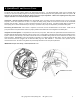
Installing the pump in the XL Series Basin or XL Basin and Cover Assembly Kit:
1. Liberty Pumps XL Series Basins as purchased separately will require the appropriate 16-bolt Pro-Series cover
assembly to make an effectively sealed ejector system. Contact the factory for the proper cover for your application.
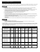
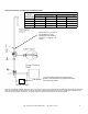
2. Size the length of the discharge piping to reach from the discharge of the pump to be within the discharge pipe socket
with integral lip seal on the underside of the Pro-Series cover. Liberty Pumps sewage pumps will use threaded-one-
end (TOE) nipples of 23.75" length for 370XL Series Basins, or 17.50" long for 380XL Series Basins. Install the pipe
into the threaded discharge of the pump.
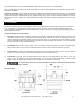
3. Lower the pump into the basin, fitting the pump legs into the Torque Stops.
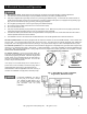
4. Insert power cord for the pump -- and the piggyback switch cord, if so equipped -- through the underside of the
inspection cover hole and position cover over pipe nipple while aligning the bolt holes. Use sixteen 1/4 - 20 UNC bolts
and washers to secure cover to the basin. Tighten bolts to 40 inch-pounds. WARNING: Do not over tighten bolts.
The soft, integral gasket will conform to the top of the tank. The bolts may be re-torqued up to 60 inch-pounds to seal
any leaks that may occur during a 10' stack test. Additionally, a small amount of RTV silicone sealant may be used
should the gasket or inserts be damaged.
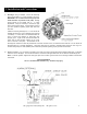
5. Liberty Pumps recommends the use of manual type pumps and the appropriate Liberty QuickTree
®
Switch Kit for
mounting of pump control and alarm floats. Contact the factory for ordering information. Install the QuickTree
®
Kit per
the instructions included. Liberty Pumps automatic type pumps with piggyback float switches may also be used. Lay
the power cable and switch cable in the grooves in the inspection cover recess as is shown in the primary instructions
as included with this system. Attach the inspection cover to the main cover using six 1/4 - 20 UNC bolts and washers.
Tighten the bolts furthest away from the power cord grooves first, torqueing to 40 inch-pounds. WARNING: Do not
over tighten bolts. The soft, integral gasket will conform to the top of the cover and power cords. The bolts may be
re-torqued up to 60 inch-pounds to seal any leaks that may occur during a 10' stack test. Additionally, a small amount
of RTV silicone sealant may be used should the gasket or inserts be damaged.
370XL and 380XL Series Basins IAPMO listed, # 4361