
Install Instructions

©Copyright 2012 Liberty Pumps Inc. All rights reserved 2
Before installation, read the following instructions carefully. Each Liberty pump is individually factory tested to insure proper
performance. Closely following these instructions will eliminate potential operating problems, assuring years of trouble-free service.
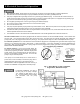
Risk of electric shock. To reduce risk of electric shock, always disconnect pump from power source before handling.
The electrical connections and wiring for a pump installation should only be made by qualified personnel.
This pump is supplied with a grounding conductor or a grounding-type attachment plug. To reduce the risk of electric shock,
be certain that the grounding conductor is connected only to a properly grounded control panel or, if equipped with a
grounding-type plug, that it is connected to a properly grounded, grounding-type receptacle.
Do not bypass grounding wires or remove ground prong from attachment plugs.
Do not remove cord and strain relief, and do not connect conduit to pump.
Do not use an extension cord.
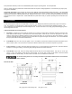
This pump requires separate, properly fused and grounded branch circuit. Make sure the power source is properly sized for
the voltage and amperage requirements of the motor, as noted on the pump nameplate.
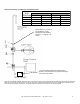
The electrical outlet or panel shall be within the length limitations of the pump power cord, and at least 4 feet above floor level
to minimize possible hazards from flood conditions.
These pumps are not to be installed in locations classified as hazardous in accordance with the National Electric Code,
ANSI/NFPA 70.
The installation must be in accordance with the National Electric Code and all applicable local codes and ordinances.
Do not use these pumps in water over 140 F.
The Uniform Plumbing Code (UPC) states that sewage systems shall have an audio and visual alarm that signals a
malfunction of the system, to reduce the potential for property damage.
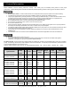
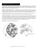
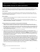
Pro-Series System: The Pro-Series 370 and 380 systems are shipped from the factory fully assembled with a wide range of possible
pumps. The following chart lists the pumps available in the Pro370 and Pro380. Your specific pump is identified by the model number
on the nameplate attached to the Pro-Series cover.
Systems ordered with alarm option have an “/A” suffix designating the alarm. “/A2” …ALM-2, “/A2W” …ALM-2W, “/A3” …ALM-3.
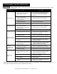
MODEL SPECIFICATIONS
System Model
Pump
Model
HP
Volts
Phase
Full Load
Amps
Solids
Handling
FNPT
Discharge
Shut-off
Head (no-flow)
P372LE41, P382LE41
P373LE41, P383LE41
LE41M
LE41M
4/10
4/10
115
115
1
1
12
12
2”
2”
2”
3”
17’
17’
P372LE51, P382LE51
P373LE51, P383LE51
LE51M
LE51M
1/2
1/2
115
115
1
1
12
12
2”
2”
2”
3”
25’
25’
P372LE52, P382LE52
P373LE52, P383LE52
LE52M
LE52M
1/2
1/2
208-230
208-230
1
1
6.8
6.8
2”
2”
2”
3”
25’
25’
P372LE71, P382LE71
P373LE71, P383LE71
LE71M
LE71M
3/4
3/4
115
115
1
1
12
12
2”
2”
2”
3”
28’
28’
P372LE72, P382LE72
P373LE72, P383LE72
LE72M
LE72M
3/4
3/4
208-230
208-230
1
1
6
6
2”
2”
2”
3”
28’
28’
P372LE102, P382LE102
P373LE102, P383LE102
LE102M
LE102M
1
1
208-230
208-230
1
7
7
2”
2”
2”
3”
36’
36’
NOTE: LEH-Series High-Head pumps require a minimum application of 15’ head.
P372LEH102, P382LEH102
P373LEH102, P373LEH102
LEH102M
LEH102M
1
1
208-230
208-230
1
1
12
12
2”
2”
2”
3”
53’
53’
1. General Information