DISCONTINUED PRODUCT POWER PROTECTION R PowerSure™ Interactive 700-2200 VA 120 V USER MANUAL English
IMPORTANT SAFETY INSTRUCTIONS WARNING: Do not attempt to service this product yourself except to replace the battery. Opening or removing the cover may expose you to dangerous voltages, even when the AC cord is disconnected from the electrical outlet. Refer all servicing to qualified service personnel. 1. SAVE THESE INSTRUCTIONS. THIS MANUAL CONTAINS IMPORTANT INSTRUCTIONS THAT SHOULD BE FOLLOWED DURING INSTALLATION AND MAINTENANCE OF THE UNINTERRUPTIBLE POWER SYSTEM (UPS) AND BATTERIES.
it, or the safety ground will be removed. Operate UPS only from a properly grounded 120 VAC outlet (2 wire plus ground). 9. The UPS is equipped with a grounded NEMA 5-15P or L5-30P input power plug (depending upon model). Do not defeat the safety purpose of this plug. If unable to fully insert the plug into the wall outlet, contact a qualified electrician for assistance. 10. Route power supply cords so they are not walked on or pinched. 11.
INTRODUCTION & SYSTEM DESCRIPTION Congratulations on your choice of the Liebert PowerSure™ Interactive Uninterruptible Power System (UPS). It provides conditioned power to microcomputers and other sensitive electronic equipment. Upon generation, AC power is clean and stable. However, during transmission it may be subject to voltage sags, spikes, or complete power failure which may interrupt computer operations, cause data loss, or even damage equipment.
MAJOR COMPONENTS TRANSIENT VOLTAGE SURGE SUPPRESSION (TVSS) AND EMI/RFI FILTERS These UPS components provide surge protection and filter Electromagnetic Interference (EMI) and Radio Frequency Interference (RFI). They minimize any surges or interference present in the utility line and keep the sensitive equipment protected. AUTOMATIC VOLTAGE REGULATOR In normal operation, the Automatic Voltage Regulator (AVR) passes utility AC power to the connected load.
MINI-TOWER INSTALLATION 1. Unpack the UPS carefully noting the packing method. Retain the box and packing material for possible future shipment. CAUTION: The UPS is heavy (see specifications). Take proper precautions when lifting or moving it. 2. Visually inspect the UPS for freight damage. Report damage to the carrier and your dealer. 3. Locate the UPS indoors where it cannot be accidentally disconnected.
RACKMOUNT INSTALLATION 1. Unpack the UPS carefully noting the packing method. Retain box and packing material for possible future shipment. CAUTION: The UPS is heavy (see specifications). precautions when lifting or moving the UPS. Take the proper 2. Visually inspect the UPS for freight damage. Report any damage to the carrier and your dealer. 3. Locate the UPS indoors where it cannot be accidentally disconnected.
CONTROLS AND INDICATORS On/Off Button The On/Off button controls output power to connected load(s). CAUTION: Pressing the On/Off button when AC utility is not present will cause the UPS to begin operating from battery. This should not be performed unless the UPS input is connected to a properly grounded receptacle. Load/Battery Level Indicators (ALL GREEN) The Load/Battery Level Indicators have dual functions.
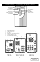
POWERSURE™ INTERACTIVE MINI-TOWER Fault Indicator Load/Battery Level Indicators Utility High/Low Indicator Alarm Silence/ Battery Test Button Utility/Battery Status Indicator On/Off Button 123456- Output Receptacles DB-9 Interface Port AC Inlet Intellislot™ Communications Port Circuit Protector or Fuse Site Wiring Fault Indicator 1 2 2 4 2 6 4 6 1 3 700 VA 5 4 5 3 1 1000 / 1400 VA 6 1 5 3 2200 VA 9 DISCONTINUED PRODUCT
POWERSURE™ INTERACTIVE RACKMOUNT Utility High / Low Indicator Fault Indicator Utility/ Battery Status Indicator Load / Battery Level Indicators R Load / Battery Utility High / Low Utility Alarm Silence On / Off Alarm Silence / Battery Test Button 2200 Model 5 3 On / Off Button 6 1 1 5 6 2 5 3 4 700-1400 Models *700 Model has detachable cord 123456- Output Receptacles DB-9 Interface Port AC Inlet Intellislot™ Communications Port Circuit Protector or Fuse Site Wiring Fault Indicator 10
OPERATION NORMAL MODE OPERATION During normal operation, utility power provides energy to the UPS. The filters and the power conditioning circuit process this power to provide computer grade power to connected loads. The UPS maintains the batteries in a fully charged state. The front panel displays the percentage of load on the UPS output. The figure below indicates approximately 51-75% loading.
BATTERY MODE OPERATION Battery mode occurs in event of extreme input conditions or complete utility failure. The battery system along with the bi-directional converter generates power for the connected load. During battery mode an alarm sounds every 10 seconds. This will change to 2 beeps every 5 seconds when battery runs low (approximately 2 minutes remaining). Each load/battery level indicator represents a 25% capacity level. As capacity decreases, fewer indicators remain illuminated.
COMMUNICATIONS INTERFACE PORT The PowerSure™ Interactive UPS contains a standard DB-9F recepticle located on the rear of the UPS unit. Several signals are provided on this port and are assigned as follows: PIN 1 2 3 4 5 6 7 8 9 ASSIGNMENT DESCRIPTION Low Battery (open collector) UPS TxD (typical RS-232 levels) UPS RxD (typical RS-232 levels) Remote Shutdown (5-12V DC, 1.0 mA. max.
UPS INTELLIGENT COMMUNICATIONS The PowerSure™ Interactive UPS has the capability to communicate intelligently with stand alone computers, network workstations, network servers, or UNIX hosts via the DB-9 female connector located on the rear of the UPS.
MINI-TOWER BATTERY REPLACEMENT CAUTION- A battery can present a risk of electrical shock and high short circuit current. The following precautions should be observed before replacing the batteries: • Turn off and disconnect the UPS from utility power prior to opening the battery replacement door. • Remove rings, watches, and other metal objects. • Use a Phillips (cross head) screwdriver with insulated grips. • Do not lay tools or other metal objects on top of the batteries.
MINI-TOWER BATTERY REPLACEMENT Pull bezel forward Rotate bezel on top Remove battery door 700 VA Model To Disconnect: Gently pull wiring away To Connect: Connect red wire to red terminal, then black wire to black terminal by pushing towards connector 1000/1400 VA Model To Disconnect: Gently pull wiring away To Connect: Connect red wire to red terminal, then black wire to black terminal by pushing upward 2200 VA Model To Disconnect: Pull apart connections A & B A B To Connect: Push connections A to
RACKMOUNT BATTERY REPLACEMENT CAUTION- A battery can present a risk of electrical shock and high short circuit current. The following precautions should be observed before replacing the batteries: • • • • • • Turn off and disconnect the UPS from utility power prior to opening the battery replacement door. Remove rings, watches, and other metal objects. Use a Phillips (cross head) screwdriver with insulated grips. Do not lay tools or other metal objects on top of the batteries.
Figure 1 Figure 2 Figure 3 Figure 5 Figure 4 Figure 7 Figure 6 18 DISCONTINUED PRODUCT
TROUBLESHOOTING The information below indicates various symptoms a user may encounter in the event the PowerSure™ Interactive UPS develops a problem. Use this information to determine whether external factors cause the problem and how to remedy the situation. 1. The fault indicator will flash every second to indicate the UPS detected a problem. 2. An alarm will sound, alerting that the UPS requires attention. 3.
PROBLEM TROUBLESHOOTING GUIDE UPS fails to start when On/Off button is pressed CAUSE UPS output short circuited or overloaded. Internal fuse is blown, indicating internal fault. Utility indicator flashing UPS not plugged in. UPS input protection has opened. Utility voltage out of UPS input range. UPS has reduced battery time Batteries not charged. UPS is overloaded. Batteries may not be able to hold a full charge due to age.
POWERSURE™ INTERACTIVE TYPICAL BATTERY DISCHARGE CURVES (Discharge times are at 25° C ambient) 700 VA 1000 VA 80 Run Time (Mins) Run Time (Mins) 80 60 40 20 0 60 40 20 0 25 50 75 0 100 0 25 Percent Load 1400 VA 100 75 100 80 Run Time (Mins) Run Time (Mins) 75 2200 VA 80 60 40 20 0 50 Percent Load 60 40 20 0 25 50 75 100 Percent Load 0 0 25 50 Percent Load 21 DISCONTINUED PRODUCT
CONDITION Battery mode (utility failure) Low battery AUDIBLE ALARM CONDITIONS ALARM Battery replacement UPS output overload UPS fault One short beep every ten seconds; more than two minutes of run time remaining Two short beeps every five seconds; less than two minutes of run time remaining Two second beep every minute One short beep every second Continuous tone FUSE REPLACEMENT PROCEDURES FOR 700 VA MODELS AC Inlet Insert flat blade screw driver into slot and pull fuse holder out to remove Fuse Hold
MINI-TOWER SPECIFICATIONS Model Number PS700MT-120 PS1000MT-120 PS1400MT-120 PS2200MT-120 Model Rating VA/W 700 / 450 1000 / 670 1400 / 950 2200 / 1600 DIMENSIONS: in (mm) 5.5 x 14.4 x 7.0 6.8 x 17.5 x 8.9 6.8 x 17.5 x 8.9 7.6 x 20.1 x 13.2 Unit (140 x 365 x 178) (172 x 447 x 227) (172 x 447 x 227) (194 x 511 x 336) WxDxH 10.5 x 19.2 x 11.75 12.0 x 22.25 x 14 12.0 x 22.25 x 14 13.0 x 25.0 x 18.5 Shipping (265 x 492 x 300) (307 x 581 x 358) (307 x 581 x 358) (330 x 635 x 470) WxDxH WEIGHT: lbs (kg) Unit 29.
RACKMOUNT SPECIFICATIONS PS700RM-120 PS1000RM-120 PS1400RM-120 PS2200RM-120 Model Number Model Rating VA/W 700 / 450 1000 / 670 1400 / 950 2200 / 1600 DIMENSIONS: in (mm) 19 x 18 x 5.25 19 x 18 x 5.25 19 x 18 x 5.25 19 x 18 x 7 Unit (483 x 457 x 133) (483 x 457 x 133) (483 x 457 x 133) (483 x 457 x 178) WxDxH 27.5 x 24 x 11 27.5 x 24 x 11 27.5 x 24 x 11 27.5 x 24 x 12 Shipping (699 x 610 x 279) (699 x 610 x 279) (699 x 610 x 279) (699 x 610 x 305) WxDxH WEIGHT: lbs (kg) Unit 41.5 (18.9) 51.29 (23.3) 57.
DISCONTINUED PRODUCT
R 1050 Dearborn Drive Columbus, OH 43229 614-888-0246 PowerSure™ Interactive 700-2200 VA 120 V Technical Support U.S.A...............................................................1-800-222-5877 Outside the U.S.A ...........................................614-841-6755 U.K................................................................ +44 (0) 1793 553355 France ...........................................................+33 1 4 87 51 52 Germany ......................................................