R UPStation GXT™ 700-3000 VA 230V USER MANUAL English / Deutsch / Français / Italiano / Español
IMPORTANT SAFETY INSTRUCTIONS WARNING: Do not attempt to service this product yourself except to replace the battery. Opening or removing the cover may expose you to dangerous voltages, even when the AC cord is disconnected from the electrical outlet. Refer all servicing to qualified service personnel. 1. SAVE THESE INSTRUCTIONS. THIS MANUAL CONTAINS IMPORTANT SAFETY INSTRUCTIONS. Read all safety and operating instructions before operating the Uninterruptible Power System (UPS).
9. The UPS output supply sockets may be electrically live whenever the input power lead is plugged into the mains supply socket. Turning the UPS off does not electrically isolate the internal parts. To isolate the UPS, turn the UPS off then isolate it from the mains supply. 10. When installing the UPS or making input and output connections, comply with relevant safety standards (e.g. IEC950, VDE0805, EN50091-1). 11.
INTRODUCTION AND SYSTEM DESCRIPTION Congratulations on your choice of the UPStation GXT™ Uninterruptible Power System (UPS). It provides conditioned power to microcomputers and other sensitive electronic equipment. Upon generation, AC power is clean and stable. However, during transmission and distribution it may be subject to voltage sags, spikes, or complete power failure which may interrupt computer operations, cause data loss, or even damage equipment.
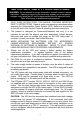
MAJOR COMPONENTS Dynamic Bypass Inverter Rectifier/PFC INPUT TVSS and EMI/RFI Filters OUTPUT DC to DC Converter Battery Charger Battery TRANSIENT VOLTAGE SURGE SUPPRESSION (TVSS) AND EMI/RFI FILTERS These UPS components provide surge protection, and filter both electromagnetic interference (EMI) and radio frequency interference (RFI). They minimize any surges or interference present in the mains line and keep the sensitive equipment protected.
DC TO DC CONVERTER The DC-DC converter utilizes energy from the battery system and raises the DC voltage to the optimum operating voltage for the inverter. This allows the inverter to operate continuously at its optimum efficiency and voltage, thus increasing reliability. BATTERY The UPStation GXT™ employs valve regulated, nonspillable, lead acid batteries. At typical room temperatures and with the UPS float charging, the battery system will last many years.
Re-plug the power input cable (A) into mains supply socket. Proceed with step 9.For 3000 VA models, a CEE 19 input cable is supplied. Proceed with the next step. 6. Connect the molded connector of the mains AC input supply cable into the UPS. 7. Fit the supplied retainer bracket around the input supply cable and secure the bracket to the rear of the UPS using the two supplied screws. 8.
RACK-MOUNT CONVERSION DIAGRAMS RACK-MOUNT UPS CONVERSION AND INSTALLATION 1. Unpack the UPS carefully noting the packing method. Retain the box and packing material for possible future shipment. 2. CAUTION: The UPS is heavy (see specifications). Take proper precautions when lifting or moving it. 3. Visually inspect the UPS for freight damage. Report damage to the carrier and your dealer. 4. Remove the two screws located at the rear of the top cover with a Phillips (cross head) screwdriver.
11. Ensure the load equipment is turned off, and plug all loads into the UPS output sockets. 12. For 700-2000 VA models, unplug power input cable from load equipment input socket and plug it into UPS input socket. Re-plug the power input cable into mains supply socket. Proceed with step 16. For 3000 VA models, a CEE 19 input cable is supplied. Proceed with the next step. 13. Connect the molded connector of the mains AC input supply cable into the UPS. 14.
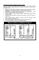
OPTIONAL BATTERY CABINET(S) INSTALLATION Up to two optional battery cabinets may be connected to the UPS to provide additional run time. Battery cabinets are designed to be placed on either side or beneath the UPS. 1. 2. 3. 4. 5. 6. 7. Unpack the UPS battery cabinet(s) carefully noting the packing method. Retain the box and packing material for possible future shipment. CAUTION: The battery cabinet(s) are heavy (see specifications). Take proper precautions when lifting or moving them.
FERRITE BEAD INSTALLATION Serial Communications Attach the smaller enclosed ferrite bead clamp to the communication cable as shown in the drawing using the following directions: • • • • Open the ferrite bead. Place the communication cable inside the ferrite bead grove. Position the ferrite beads as close as possible to the end of the cable that connects to the DB9 connector of the UPS. Close the ferrite bead so that the ferrite bead’s case snaps closed with the cable routed inside the ferrite bead’s case.
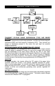
UPSTATION GXT™ Fault Indicator Bypass Indicator UPS On Indicator Battery Indicator AC Input Indicator Load/Battery Level Indicators On/Alarm Silence/ Manual Battery Test Button Off/ Bypass Button 1- Output Receptacles 2- DB-9 Interface Port 3- AC Inlet 4- Intellislot TM Communications Port 5- Circuit Protector or fuse 6- Output Voltage Selector Switches 7- Battery Cable Connector 6 2 4 6 2 4 6 2 4 5 6 2 4 3 3 5 3 5 5 7 7 7 1 3 1 3 700/1000 VA Mini-Tower 1000/1500 VA Rack Tower 2
CONTROLS AND INDICATORS On/Alarm Silence/Manual Battery Test Button This button controls output power to connected load(s) and has three functions: On, Alarm Silence, and Manual Battery Test. Pressing this button will start up the UPS in order to provide conditioned and protected power into the mains socket. To silence alarms, press this button for at least one half second while alarm conditions are present.
UPS On Indicator (Green) The UPS On indicator is illuminated when the UPS inverter is operating and supplying power to your connected loads. Battery Indicator (Amber)The Battery indicator is illuminated when the UPS is operating from the battery system. AC Input Indicator (Green) The AC Input indicator is illuminated when mains power is available and within the input specification.
BATTERY MODE OPERATION Battery mode occurs in event of an extreme input voltage condition or complete mains failure. The battery system supplies power through the DC-DC converter to the inverter to generate power for the connected load. During battery mode an alarm sounds every 10 seconds. This will change to 2 beeps every 5 seconds when battery runs low (approximately 2 minutes remaining). The AC Input LED will extinguish, and the Battery LED will illuminate to warn that a mains problem has occurred.
COMMUNICATIONS INTERFACE PORT The UPStation GXT™ UPS contains a standard DB-9 female connector located on the rear of the UPS unit.
UPS INTELLIGENT COMMUNICATIONS The UPStation GXT™ UPS has the capability to communicate intelligently with stand alone computers, network workstations, network servers, or UNIX hosts via the DB-9 female connector located at the rear of the UPS.
BATTERY REPLACEMENT PROCEDURES CAUTION – A battery can present a risk of electrical shock and high short circuit current. The following precautions should be observed before replacing the batteries: Turn off and disconnect the UPS from the mains power prior to opening the battery replacement door. Remove rings, watches, and other metal objects. Use a Phillips (cross head) screwdriver with insulated grips. Do not lay tools or other metal objects on top of the batteries.
8. 9. Carefully stand the UPS upright. Connect the UPS to the mains supply socket and turn on the UPS by pressing the on button. The UPS is ready for normal operation. Dispose of batteries in accordance with your local laws and regulations. FOR 1000 TO 3000 VA RACK/TOWER MODELS: CAUTION: The battery assembly is heavy. Take proper precautions when lifting or moving it. TOWER MODELS ONLY: Remove top cover by removing the two screws located on rear of top cover.
RACK / TOWER BATTERY REPLACEMENT Top cover screws Flange screws Rear View Aerial View w/top cover removed Two front rubber feet Front bezel (cover) Small battery door Large battery door Screw hidden by small battery door Large battery door 20 Battery connector
UPSTATION GXT BATTERY RUN TIMES (Discharge times are at 25° C ambient) Internal Battery (minutes) Load% 700MT 1000MT 1000RT 1000RTE 1500RT 2000RT 3000RT 10% 20% 30% 40% 50% 60% 70% 80% 90% 100% 52 40 32 24 18 15 12 10 8 6 94 45 33 24 18 14 12 9 7 6 94 45 33 24 18 14 12 9 7 6 169 127 94 68 49 36 28 23 19 17 78 39 27 20 15 11 9 7 6 5 160 83 47 34 27 21 18 15 13 11 101 51 28 20 15 12 10 8 7 6 Internal Battery + 1 External Battery Cabinet (minutes) Load% 700MT 1000MT 1000RT 1000RTE 1500RT
FUSE REPLACEMENT PROCEDURES CAUTION: Before changing the input fuse, turn off the UPS, and unplug the supply lead from the AC input supply and from the UPS. Replace the fuse with the same type and rating. Insert flat blade screwdriver into slot and turn fuse holder to remove / install Input Fuse Fuse Holder Remove Install 1. Remove the fuse holder by inserting a flat blade screwdriver into the slot and turning to remove as indicated in the figure above. 2. Remove the input fuse. 3.
TROUBLESHOOTING The information below indicates various symptoms a user may encounter in the event the UPStation GXT™ develops a problem. Use this information to determine whether external factors cause the problem and how to remedy the situation. 1. 2. 3. The fault indicator will illuminate indicating the UPS detected a problem. An alarm will sound, alerting that the UPS requires attention.
TROUBLESHOOTING GUIDE PROBLEM UPS fails to start when on button is pressed Battery indicator is illuminated CAUSE SOLUTION UPS is short circuited or overloaded Internal fuse is blown, indicating internal fault UPS not plugged in UPS input protection has opened Mains voltage out of UPS input range.
SPECIFICATIONS MODEL NUMBER GXT700MT-230 GXT1000MT-230 MODEL RATING VA/W 700 / 490 1000 / 700 DIMENSIONS: mm (in) Unit 162 x 430 x 225 162 x 430 x 225 WxDxH (6.4 x 15.6 x 8.9) (6.4 x 15.6 x 8.9) Shipping 280 x 502 x 362 280 x 502 x 362 WxDxH (11.0 x 19.75 x 14.25) (11.0 x 19.75 x 14.25) WEIGHT: kg (lbs) Unit 13.1 (28.8) 15.8 (34.8) Shipping 15.0 (33.0) 17.7 (39.
SPECIFICATIONS MODEL NUMBER GXT1000RT-230 GXT1000RTE-230 MODEL RATING VA/W 1000 / 700 1000 / 700 DIMENSIONS: mm (in) Unit 177 x 522 x 430 177 x 522 x 430 WxDxH (7.0 x 19.3 x 16.9) (7.0 x 19.3 x 16.9) Shipping 340 x 660 x 565 340 x 660 x 565 WxDxH (13.38 x 26.0 x 22.25) (13.38 x 26.0 x 22.25) WEIGHT: kg (lbs) Unit 23.6 (51.9) 31.1 (68.4) Shipping 26.8 (59.0) 34.3 (75.
SPECIFICATIONS MODEL NUMBER GXT1500RT-230 GXT2000RT-230 GXT3000RT-230 MODEL RATING VA/W 1500 / 1050 2000 / 1400 3000 / 2100 DIMENSIONS: mm (in) Unit 177 x 522 x 430 177 x 522 x 430 177 x 522 x 430 WxDxH (7.0 x 19.3 x 16.9) (7.0 x 19.3 x 16.9) (7.0 x 19.3 x 16.9) Shipping 340 x 660 x 565 340 x 660 x 565 340 x 660 x 565 WxDxH (13.38 x 26.0 x 22.25) (13.38 x 26.0 x 22.25) (13.38 x 26.0 x 22.25) WEIGHT: kg (lbs) Unit 27.7 (60.9) 36.8 (80.9) 39.0 (85.9) Shipping 30.9 (68.0) 40.0 (88.0) 42.3 (93.
BATTERY CABINET SPECIFICATIONS MODEL NUMBER GXT36VBATT GXT48VBATT Used w/ UPS Model 1000RT 1500RT DIMENSIONS: in (mm) Unit 177 x 522 x 430 177 x 522 x 430 WxDxH (7.0 x 19.3 x 16. 9) (7.0 x 19.3 x 16. 9) Shipping 13.38 x 26.0 x 22.25 13.38 x 26.0 x 22.25 WxDxH (340 x 660 x 565) (340 x 660 x 565) WEIGHT: lbs (kg) Unit 61.3 (27.9) 71.6 (32.5) Shipping 68.4 (31) 78.7 (35.7) BATTERY PARAMETERS Type Valve-regulated, nonspillable, lead # of Strings x Qty/Str. x Batt. Voltage x Batt. Rating Batt. Mfg.
LIMITED WARRANTY Liebert Corporation extends the following LIMITED WARRANTY to the purchaser and to its customer (collectively referred to as the "Purchaser"): the enclosed Uninterruptible Power System (UPS) and components are free from defects in materials and workmanship under normal use, service, and maintenance FOR A PERIOD OF TWO YEARS FROM THE DATE OF ORIGINAL PURCHASE from Liebert or the Liebert dealer or retailer.
R 1050 Dearborn Drive Columbus, OH 43229 614-888-0246 UPStation GXT™ 700-3000 VA 230 V Technical Technical Support U.S.A. Outside the U.S.A. U.K. France Germany Italy Netherlands E-mail Web site Worldwide FAX tech support 1-800-222-5877 614-841-6755 +44 (0) 1793 553355 +33 1 4 87 51 52 +49 89 99 19 220 +39 2 98250 1 +00 31 475 503333 upstech@liebert.com http://www.liebert.