MONITORING AC4 USER MANUAL
TABLE OF CONTENTS 1.0 INTRODUCTION 1.1 1.2 1.3 1.4 1.5 1.6 1.7 1.8 Methods of Viewing and Configuring the AC4 . . . . . . . . . . . . . . . . . . . . . . . . . . . . . . . . . . . . . Data Logs . . . . . . . . . . . . . . . . . . . . . . . . . . . . . . . . . . . . . . . . . . . . . . . . . . . . . . . . . . . . . . . . . . Available Alarms . . . . . . . . . . . . . . . . . . . . . . . . . . . . . . . . . . . . . . . . . . . . . . . . . . . . . . . . . . . . Outside Enclosure Overview . . . . . . . . . .
6.0 SILENCE ALARM & BACKUP LOG FILES (SERVICE TERMINAL INTERFACE) 6.1 6.2 Silence Alarm (Service Terminal Interface) . . . . . . . . . . . . . . . . . . . . . . . . . . . . . . . . . . . . . . 23 Back Up Log Files (Service Terminal Interface only) . . . . . . . . . . . . . . . . . . . . . . . . . . . . . . . 24 7.0 SYSTEM AND CONTROL OPTIONS 7.1 7.2 7.3 Login . . . . . . . . . . . . . . . . . . . . . . . . . . . . . . . . . . . . . . . . . . . . . . . . . . . . . . . . . . . . . . . . . . . . .
APPENDIX A - SERVICE TERMINAL INTERFACE . . . . . . . . . . . . . . . . . . . . . . . . . . . . . . . . . . . . . . . 49 A.1 A.2 Comparison of Functions: LCD and Service Terminal Interface. . . . . . . . . . . . . . . . . . . . . . 49 Connecting to the Service Terminal Interface . . . . . . . . . . . . . . . . . . . . . . . . . . . . . . . . . . . . 50 A.2.1 A.2.2 A.3 Overview of Menus . . . . . . . . . . . . . . . . . . . . . . . . . . . . . . . . . . . . . . . . . . . . . . . . . . . . . . . . . .
FIGURES Figure 1 AC4 enclosure—external features . . . . . . . . . . . . . . . . . . . . . . . . . . . . . . . . . . . . . . . . . . . . . . . . . . . 2 Figure 2 AC4 enclosure—internal features . . . . . . . . . . . . . . . . . . . . . . . . . . . . . . . . . . . . . . . . . . . . . . . . . . . 2 Figure 3 Typical Configuration . . . . . . . . . . . . . . . . . . . . . . . . . . . . . . . . . . . . . . . . . . . . . . . . . . . . . . . . . . . . . 3 Figure 4 Example of typical sequence. . . . . . . .
Introduction 1.0 INTRODUCTION The Liebert AC4 is ideal for coordinated control of systems with redundant equipment, such as multiple environmental units or pumps. When the AC4 controller detects an alarm in an operating device, the AC4 enables a standby device and controls the device in alarm as configured, either leaving that device operating or disabling it. The AC4 controller can also balance usage of devices by rotating units through Operating and Standby modes according to a user-defined schedule.
Introduction 1.4 Outside Enclosure Overview The AC4’s controller board comes in an enclosure that is 2-3/4" deep and has a built-in liquid crystal display (LCD) and a key lock, as shown in Figure 1. The enclosure is made of metal to accommodate secure conduit fittings and protect components against environmental debris. Figure 1 AC4 enclosure—external features LCD for configuration and operation The enclosure has knockouts and access slots on top and bottom for cables and wires.
Introduction 1.5 Typical Configuration Figure 3 shows an example of external devices connected to the AC4’s controller board. There may be up to four devices connected to the four digital inputs and four digital outputs. Remote access is available through the Service Terminal Interface.
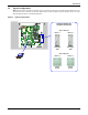
Introduction 1.6 Controller Board Overview The AC4’s controller board has connectors for four digital inputs and four digital outputs, as shown below. The board comes complete with light emitting diodes (LEDs) to display the status of connected devices, a serial communications port, a power connection and other features necessary to control your operation.
Introduction Table 1 Controller board components (continued) Item Description For more information, see: I - Digital output loss-of-power jumper One of four output jumpers. Each digital output has a jumper to set the fail-safe position of the output point when power fails. The OFF position makes the contact Normally Open (factory default). The ON position makes the contact Normally Closed. Note: The jumper position has no effect on the contact when the AC4 has power. 3.2.
Introduction 1.
Introduction 1.8 Typical Sequence Figure 4 shows a typical sequence of how the AC4 functions after detecting a change in a monitored device. Many responses depend on configuration settings. This example shows what happens when a digital input changes state—assuming the input is defined as alarmable—and when the condition returns to normal. Figure 4 Example of typical sequence RESPONSES TO AN ALARM UNIVERSAL MONITOR 05-SEP-02 14:04:13 V5.100.
Installation 2.0 INSTALLATION 2.1 Installation Considerations The AC4 must be installed indoors and may be mounted on the surface of a wall or flush-mounted, depending on the user’s application, the location of equipment to be connected and the type of wall the unit will be mounted on. The AC4 should be mounted where it can be easily accessed. On-site personnel would access the unit through the LCD on its front cover or the service terminal connected to the RS232 port.
Installation 2.2 Surface-Mounting the AC4 NOTE Removing the conduit knockouts before mounting the AC4 on the wall will ease installation and prevent strain on the mounting hardware and wall. It is imperative to remove the knockouts if the unit is to be flush-mounted. After determining where to place the unit, check to ensure that you have all the hardware required to install the panel on the surface of a wall. Obtain the needed tools and material. Required tools • • • • 2.2.
Installation 2.3 Flush-Mounting the AC4 NOTE Removing the conduit knockouts before mounting the AC4 on the wall will ease installation and prevent strain on the mounting hardware and wall. It is imperative to remove the knockouts if the unit is to be flush-mounted. The rectangular access doors on the top and bottom of the AC4 must be reversed so they slide the opposite direction. Leaving the doors as shipped from the factory prevents them from being opened when the panel is flush mounted in a wall.
Installation 2.4 Connect Power to the AC4 The AC4 requires 24VAC for proper operation. Liebert recommends using the optional Transformer Module manufactured by Liebert or another UL-approved class 2 power unit to obtain proper voltage. If the power unit is not a class 2 circuit, it must be protected with an IEC 5 x 20mm time lag 2A fuse. For information, consult your local dealer, Liebert representative or the Liebert Worldwide Support Group.
Wiring and Connections 3.0 WIRING AND CONNECTIONS CAUTION ! 3.1 Switch OFF electric power to the AC4 before installing any wiring to the unit or changing input or output connections. The Power On/Off switch is in the top left corner of the unit. Wiring Specifications Input and output connections to the AC4 may be made in any order—it is not necessary, for example, to make all input connections before making any output connections. Use copper conductors only for all wiring.
Wiring and Connections 3.2 Connecting Digital Inputs and Outputs The digital inputs and outputs are found on the lower right side of the AC4’s printed wiring assembly board. This section describes how to connect devices to the AC4’s inputs and outputs.
Wiring and Connections 3.2.3 Setting the Digital Output Jumpers Digital output jumpers (four) Each digital output has an associated jumper to define its operation when power is interrupted. This puts the AC4 in a fail-safe mode and ensures proper functioning when the board has no power. The AC4 comes from the factory with all digital output jumpers in the OFF position (normally open). The jumper setting for each digital output can be changed to ON (normally closed). The settings are shown in Table 5.
Overview of Menus 4.0 OVERVIEW OF MENUS There are two ways to access the AC4: the LCD on the front of the enclosure and the Service Terminal Interface, which is accessible through any computer using a communications program. Many viewing and configuration tasks can be performed through either interface, but some are available only through the Service Terminal Interface. • Step-by-step instructions for all functions appear in Sections 5.0 through 7.0.
Overview of Menus 4.1 Opening Screen Overview The AC4 displays the Opening Screen at startup, as shown in Figure 7. • If any alarms are active, the Current Alarm screen appears. (Pressing any key on the LCD keypad will silence the audible alarm.) If no alarms are present, the Main Menu appears. 4.2 Main Menu Overview The Main Menu offers access to all functions within the panel. As shown in Table 7, the functions are organized into three sections with step-by-step instructions.
View Status Options 5.0 VIEW STATUS OPTIONS NOTE For ease of understanding, this section uses the LCD interface to illustrate most instructions, except for features that are available only through the Service Terminal Interface. All Service Terminal Interface screens appear in Appendix A - Service Terminal Interface. The View Status menu allows any user to view currently active alarms, data stored in the alarm and event logs and the status of all inputs and outputs.
View Status Options 5.1 View Active Alarms Main Menu The Active Alarm screen displays all alarms that are occurring, up to a > VIEW STATUS SYSTEM AND CONTROL maximum of 40. ↑↓=NEXT ↵=SELECT A Current Alarm screen appears automatically whenever an alarm occurs—except during setup. This screen can display only the two most recent active alarms. To view any other active alarms, use the View View Status Menu Active Alarms feature.
View Status Options 5.2 View Alarm Log Main Menu The Alarm Log contains up to 99 records of alarms that have occurred. > VIEW STATUS SYSTEM AND CONTROL Records are added to this log as alarms occur. To view the Alarm Log: ↑↓=NEXT • From the Main Menu, use the arrows ↑↓ to choose View Status, then press Enter ↵. • From the View Status Menu, use the arrows ↑↓ to choose View Alarm Log, then press Enter ↵. 5.2.
View Status Options 5.3 View Event Log Main Menu In addition to alarms, the AC4 tracks other changes in the Event Log to > VIEW STATUS SYSTEM AND CONTROL assist users with verifying operational and troubleshooting problems. Events reflect changes in the status of an input that is defined as an event ↑↓=NEXT ↵=SELECT or the change of state of an output (i.e., manually forced ON or OFF). Other events may be informational, such as a user login.
View Status Options 5.4 View Input Status Main Menu The Input Status option allows you to view the current status of all four > VIEW STATUS SYSTEM AND CONTROL digital inputs. To view the Input Status: ↑↓=NEXT • From the Main Menu, use the arrows ↑↓ to choose View Status, then press Enter ↵. • From the View Status Menu, use the arrows ↑↓ to choose View Input Status, then press Enter ↵. 5.4.1 Input Status The Input Status screen displays the status of each digital input.
View Status Options 5.5 View Output Status Main Menu The Output Status option allows you to view the current status of all four outputs. > VIEW STATUS SYSTEM AND CONTROL To view the Output Status: ↑↓=NEXT • From the Main Menu, use the arrows ↑↓ to choose View Status, then press Enter ↵. • From the View Status Menu, use the arrows ↑↓ to choose View Output Status, then press Enter ↵. 5.5.1 Output Status The Output Status screen displays the status of each digital output.
Silence Alarm & Backup Log Files (Service Terminal Interface) 6.0 SILENCE ALARM & BACKUP LOG FILES (SERVICE TERMINAL INTERFACE) This section describes two features that are available in the Service Terminal Interface: • Silence Alarm • Backup Log Files 6.1 Silence Alarm (Service Terminal Interface) The Silence Alarm menu item allows you to silence the audible alarm and reset the Common Alarm Relay output if the common alarm is configured to reset with silence.
Silence Alarm & Backup Log Files (Service Terminal Interface) 6.2 Back Up Log Files (Service Terminal Interface only) The AC4 maintains two types of logs—alarm and event—that may be backed up to a remote computer. This feature is available only through the Service Terminal Interface. To back up the alarm or event log: 1. Connect to the AC4 through the RS232 port (see A.2 - Connecting to the Service Terminal Interface). 2. At the Main Menu, enter 7 (Backup Log Files). 3.
Silence Alarm & Backup Log Files (Service Terminal Interface) NOTE The following instructions refer to the Microsoft® Windows® HyperTerminal program. These steps may vary for other communications programs. 5. At the top of the HyperTerminal window, shown below, click on Transfer, then on Receive File. Enter folder Select Xmodem Enter filename for example, event.log 6.
System and Control Options 7.0 SYSTEM AND CONTROL OPTIONS NOTE For ease of understanding, this section uses the LCD interface to illustrate most instructions, except for features that are available only through the Service Terminal Interface. All Service Terminal Interface screens appear in Appendix A - Service Terminal Interface. The System and Control menu allows you to configure the AC4—setting up inputs and outputs and system features such as date and time.
System and Control Options Figure 9 shows the main options available from the System & Control menu. Figure 9 Menu overview - System and Control menu Opening Screen LIEBERT AC4 DD-MON-YY HR:MM:SS VX.XXX.
System and Control Options 7.2 Setup System - Overview The Setup System screen displays six options that allow you to configure input and output devices, the common alarm, and a variety of system details, such as login password and system date and time: • • • • • • 7.3 Setup Inputs Setup Common Alarm Setup Zones Setup Outputs Setup System Info Setup Operation Setup System Menu Setup System - Setup Inputs The AC4 has four digital input points that may be configured individually.
System and Control Options 7.3.1 Change Label (Name of Input) Setup Inputs Menu Each input has a default label (Device_1, Device_2, etc.) that you may change to a more descriptive name for ease in recognizing alarms and events associated with the input. The label may consist of up to eight characters (see Table 12 for valid characters). The device name assigned through this menu is also displayed for the corresponding output.
System and Control Options 7.3.4 Set Up Alarmable Inputs in Latched or Unlatched Mode Setup Inputs Menu Alarmable input points may be set up in Latched mode (Y), which requires the user to clear the AC4 alarms after an alarm has occurred, or Unlatched mode (N), in which alarms will automatically clear after a return-to-normal state. The default setting for alarmable inputs is Y (Latched). Any input defined as an event is automatically Unlatched.
System and Control Options 7.4 Setup System - Setup Common Alarm The audible alarm sounds after the AC4 detects an alarm condition in any input that has been defined as alarmable. Once the alarm is silenced, there are two options: • By default, the common alarm remains energized until all input alarms are cleared. • You may change this setting to de-energize the common alarm automatically once the alarm is silenced.
System and Control Options 7.5 Setup System - Setup Zones The AC4 has two zones that may be used to define different areas—rooms or sections of a room. The AC4 effectively performs as two separate units, controlling each zone separately, for examply, using a different rotation sequence for devices in each zone. Each zone may have two to four outputs associated with it. By default, Zone 1 has four associated outputs and Zone 2 has none.
System and Control Options 7.6 Setup System - Setup Outputs The AC4 has four outputs that may be configured individually. These outputs correspond to the four numbered inputs. For example, Device_1 is the unit connected to Input 1 and to Output 1. The output name is the same as the input name, as described in 7.3.1 Change Label (Name of Input). To configure an output: Log In and Choose Setup System • From the Main Menu, use the arrows ↑↓ to choose System and Control, then press Enter ↵ (see 7.
System and Control Options 7.6.2 Define Operating or Standby Mode Setup Outputs Menu Each output may be defined as Operating (OP), Standby (ST), or Not Used (NU). This setting takes precedence over any setting in the override menu (see 7.9 - Override Output).
System and Control Options 7.
System and Control Options 7.7.2 Set Date & Time/Automatic Daylight Saving Time The AC4 has a built-in real-time clock that is backed up by an encapsulated lithium battery and set up to adjust automatically for daylight saving time twice a year. The Setup System Info menu allows you to set the current date or time or change the automatic adjustment at any time.
System and Control Options 7.7.4 Backup and Upload Configuration File (Service Terminal Interface only) This operation may be performed only through the Service Terminal Interface. It permits the user to make a copy of the AC4’s configuration settings and save it as a file on the computer connected through the RS232 port. Should the need arise, the user can upload the configuration file from the computer to the AC4, instead of re-entering the settings manually. To access these options: 1.
System and Control Options Back Up the Configuration File 8. At the prompt to Initiate a Backup of Configuration File, enter Y (Yes - begin) or N (No - cancel). The current setting appears in brackets—[N] in the following example. >INITIATE A BACKUP OF CONFIGURATION FILE-YES(Y) OR NO(N)? >[N] >[ NOTE The following instructions refer to the Microsoft Windows HyperTerminal program. These steps may vary for other communications programs. 9.
System and Control Options Upload the Configuration File 13. At the prompt to Initiate an Upload of Configuration File, enter Y (Yes - begin) or N (No - cancel). The current setting appears in brackets—[N] in the following example. >INITIATE AN UPLOAD OF CONFIGURATION FILE-YES(Y) OR NO(N)? >[N] >[ NOTE The following instructions refer to the Microsoft Windows HyperTerminal program. These steps may vary for other communications programs. 14.
System and Control Options 7.7.5 Factory Defaults Setup System Info Menu At any time, you may restore all default values for settings in the AC4 as it was shipped. NOTE This action will overwrite any configuration settings. You may want to back up your settings before restoring the factory defaults. See Backup and Upload Configuration File (Service Terminal Interface only) in A.6.5 - Setup System Info for details on backing up settings using the Service Terminal Interface.
System and Control Options NOTE The following instructions refer to the Microsoft Windows HyperTerminal program. These steps may vary for other communications programs. 2. The firmware update is a two-step process—this step describes how to upload the file prog###.s19 (where ### is a number—for example, prog118.s19) to the AC4: a. At the top of the HyperTerminal window, shown below, click on Transfer, then on Send File. Enter filename prog###.s19 or flash###.s19 Select Xmodem Send button b.
System and Control Options 7.8 Setup Operation The AC4’s operation features allow you to set up a rotation sequence to Setup System Menu alternate which devices are operating and which are placed on SETUP INPUTS Standby, as well as test devices while in Standby mode and specify SETUP COMMON ALARM what to do when a Standby device goes into alarm as it is powered up.
System and Control Options 7.8.1 Turn Automatic Sequencing On or Off Use automatic sequencing to set up a schedule for rotation of redundant devices. For example, three devices might be in operating mode while a fourth device is in standby mode. Every two days, the AC4 returns the standby device to operating mode and places one of the operating devices on standby.
System and Control Options 7.8.2 Turn Standby Testing On or Off Standby testing permits scheduling an automatic operational check of devices in Standby mode. When this feature is activated (ON), the AC4 tests all devices in Standby mode by putting each device in operating mode for a designated time. You may specify the time of day the testing begins, the duration of the test and the interval between tests. Standby testing is OFF (deactivated) by default.
System and Control Options 7.8.4 Specify Hold Delay Time Setup Operation Menu After an output changes state, the hold delay timer directs the AC4 to ignore all inputs in the same zone for the specified time. This delay is the amount of time that must elapse before the AC4 acknowledges a change of state in any input. The default is 10 minutes (displayed as 10 MIN : 00 SEC).
System and Control Options 7.9 Override Output The Override Output feature allows you to manually change the state of any digital output to ON or OFF, overriding automatic control by the AC4 (the default setting for all outputs). This menu also allows you to release the manual override, returning any output to automatic control. There are two ways to override automatic control of outputs: • Use the Override Output menu, as described in this section, to turn any output ON or OFF.
System and Control Options 7.10 Clear Alarms & Logs Main Menu The Clear Alarms & Logs menu allows you to clear active alarms or delete all records from either of the AC4’s alarm and event logs. VIEW STATUS > SYSTEM AND CONTROL ↑↓=NEXT To clear alarms or logs: Log In and Choose Clear Alarms & Logs • From the Main Menu, use the arrows ↑↓ to choose System and Control, then press Enter ↵ (see 7.1 - Login for help). • Enter your password at the Login screen.
Specifications 8.0 SPECIFICATIONS 8.1 AC4 Specifications Power Requirements 24VAC ±10% of nominal 50/60 Hz 1.3A, 30VA Dimensions W x D x H, in. (mm) 14-1/4 x 2-3/4 x 12 (361.95 x 69.85 x 304.8) Weight (Assembled) 7.68 lbs (3.
Comparison of Functions: LCD and Service Terminal Interface APPENDIX A - SERVICE TERMINAL INTERFACE The Service Terminal Interface allows access to all functions of the AC4, including some that are not possible through the LCD interface. This interface is accessible through any computer using a communications program such as Microsoft® Windows® HyperTerminal.
Connecting to the Service Terminal Interface A.2 CONNECTING TO THE SERVICE TERMINAL INTERFACE This section describes how to set up and connect to the Service Terminal Interface. To access the Service Terminal Interface, you will need: • A null modem cable to connect a computer’s COM1 port to the AC4’s RS232 port. • A communications program, such as HyperTerminal, to connect to the Service Terminal Interface.
Connecting to the Service Terminal Interface A.2.1 Create a Connection Before connecting to the Service Terminal Interface, you must create a connection and specify the method to be used for connection, as described in the following steps. 1. Start the HyperTerminal program—to do this, click on the Start button, then on Programs, then Accessories, then Communications, and finally HyperTerminal. 2. At the top of the HyperTerminal window, click on File, then on New Connection, as shown below left.
Connecting to the Service Terminal Interface Properties Setup 9. Open the Properties window by clicking on File, then on Properties, as shown below left. Settings tab 10. In the Properties window, above right, click on the Settings tab and choose the following settings: • Function, arrow, and ctrl keys act as: Terminal keys • Backspace key sends: Ctrl+H • Emulation: ANSIW • Telnet terminal ID: VT100 • Backscroll buffer lines: 500 • Play sound when connecting or disconnecting: Unchecked ASCII Setup 11.
Connecting to the Service Terminal Interface A.2.2 Connect to the Service Terminal Interface After creating and setting up a connection, use a communications program such as HyperTerminal to access the AC4’s Service Terminal Interface. 1. Verify communications connections between the remote computer and the AC4. Connect a null modem cable from the computer’s COM1 port to the AC4’s RS232 port (for location, see 3.4 RS232 Connector). 2.
Overview of Menus A.3 OVERVIEW OF MENUS The Main Menu offers choices for viewing the status of the AC4, silencing the audible alarm and backing up the unit’s log files. It also allows access to the System and Control features, which require a password. The following shows where to find examples of the Main Menu screens: Main Menu 1=VIEW ACTIVE ALARMS For sample screens, see: A.4 - View Status Menus 2=VIEW ALARM LOG 3=VIEW EVENT LOG 4=VIEW INPUT STATUS 5=VIEW OUTPUT STATUS 7=BACKUP LOG FILES A.
View Status Menus A.4 VIEW STATUS MENUS The View Status menu allows any user to view currently active alarms, data stored in the alarm and event logs and the status of all inputs and outputs. Main Menu After connecting to the Service Terminal Interface, the Main Menu appears, as shown below. This section presents Service Terminal Interface screens for options 1 through 5: Main Menu LIEBERT AC4 VX.XXX.
View Status Menus A.4.1 View Active Alarms For details on this feature, see 5.1 - View Active Alarms.
View Status Menus A.4.2 View Alarm Log For details on this feature, see 5.2 - View Alarm Log.
View Status Menus A.4.3 View Event Log For details on this feature, see 5.3 - View Event Log.
View Status Menus A.4.4 View Input Status For details on this feature, see 5.4 - View Input Status.
View Status Menus A.4.5 View Output Status For details on this feature, see 5.5 - View Output Status.
Silence Alarm & Back Up Log Files (Service Terminal Interface only) A.5 SILENCE ALARM & BACK UP LOG FILES (SERVICE TERMINAL INTERFACE ONLY) This section presents two options from the Main Menu that are available via the Service Terminal Interface only. Main Menu After connecting to the Service Terminal Interface, the Main Menu appears, as shown below. This section presents Service Terminal Interface screens for options 6 and 7: Main Menu LIEBERT AC4 V5.300.
Silence Alarm & Back Up Log Files (Service Terminal Interface only) A.5.2 Back Up Log Files (Service Terminal Interface only) For details on this feature, see 6.2 - Back Up Log Files (Service Terminal Interface only).
Setup Menu A.6 SETUP MENU The Setup menu allows the user to configure the AC4—setting up inputs, outputs and system features such as date and time, as well as operation options such as a rotation sequence and standy testing. This menu also provides a vehicle for manually changing the state of an output to ON or OFF, clearing active alarms and deleting records from the AC4’s alarm and event logs. Main Menu After connecting to the Service Terminal Interface, the Main Menu appears, as shown below.
Setup Menu Setup Menu This section presents Service Terminal Interface screens for each of the following: Setup Menu See: Description 1=SETUP INPUTS Section A.6.1 Configure digital inputs 2=SETUP COMMON ALARM Section A.6.2 Set up the common alarm to reset with silence 3=SETUP ZONES Section A.6.3 Define areas with 2-4 devices each 4=SETUP OUTPUTS Section A.6.4 Configure digital outputs 5=SETUP SYSTEM INFORMATION* Section A.6.
Setup Menu A.6.1 Setup Inputs For details on this feature, see 7.3 - Setup System - Setup Inputs.
Setup Menu A.6.2 Setup Common Alarm For details on this feature, see 7.4 - Setup System - Setup Common Alarm.
Setup Menu A.6.3 Setup Zones For details on this feature, see 7.5 - Setup System - Setup Zones.
Setup Menu A.6.4 Setup Outputs For details on this feature, see 7.6 - Setup System - Setup Outputs.
Setup Menu A.6.5 Setup System Info This section presents Service Terminal Interface screens for choices 1 through 9 in the Setup System Information menu shown below. For details on this topic, see 7.7 - Setup System - Setup System Info.
Setup Menu Set Date & Time/Automatic Daylight Saving Time For details on this feature, see 7.7.2 - Set Date & Time/Automatic Daylight Saving Time.
Setup Menu Backup and Upload Configuration File (Service Terminal Interface only) For details on this feature, see 7.7.4 - Backup and Upload Configuration File (Service Terminal Interface only).
Setup Menu Backup & Upload Configuration File - Upload BACKUP AND UPLOAD CONFIGURATION FILE Backup from panel saves panel configurations Upload to panel restores panel configurations Select to backup or upload file 1=BACKUP 2=UPLOAD 3=RETURN 4=RETURN 5=RETURN CONFIGURATION FILE CONFIGURATION FILE TO SETUP SYSTEM INFO MENU TO SETUP MENU TO MAIN MENU SELECT A NUMBER:2 >INITIATE AN UPLOAD OF CONFIGURATION FILE-YES(Y) OR NO(N)? >[N] >[ INSTRUCTIONS TO PERFORM UPLOAD: ASSUMES USING MICROSOFT WINDOWS HYPERTERM
Setup Menu Firmware Update (Service Terminal Interface only) For details on this feature, see 7.7.6 - Perform Firmware Update (Service Terminal Interface only).
Setup Menu A.6.6 Setup Operation For details on this feature, see 7.8 - Setup Operation. Auto Sequencing For details on this feature, see 7.8.1 - Turn Automatic Sequencing On or Off.
Setup Menu Standby Testing For details on this feature, see 7.8.2 - Turn Standby Testing On or Off.
Setup Menu Failed Standby For details on this feature, see 7.8.3 - Specify Failed Standby Response.
Setup Menu Restart Delay For details on this feature, see 7.8.5 - Specify Restart Time.
Setup Menu A.6.7 Override Output For details on this feature, see 7.9 - Override Output.
Setup Menu A.6.8 Clear Alarms & Logs For details on this topic, see 7.10 - Clear Alarms & Logs. Clear Active Alarms For details on this feature, see 7.10.1 - Clear Active Alarms.
Setup Menu Clear the Event Log For details on this feature, see 7.10.3 - Clear the Event Log.
MONITORING AC4 The Company Behind the Products With over a million installations around the globe, Liebert is the world leader in computer protection systems.