Precision Cooling For Business-Critical Continuity™ Liebert XDV™ User Manual–50 & 60 Hz
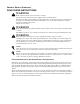
GENERAL SAFETY GUIDELINES SAVE THESE INSTRUCTIONS ! WARNING Risk of electric shock. Can cause injury or death. Disconnect local and remote power supplies before working within. Before proceeding with installation of XD cooling unit’s, read all instructions, verify that all the parts are included, and check the nameplate to be sure the XD cooling unit’s voltage matches available utility power. Follow all local codes. ! WARNING Risk of unit falling over when installed on top of cabinet.
TABLE OF CONTENTS GENERAL SAFETY GUIDELINES . . . . . . . . . . . . . . . . . . . . . . . . . . . . . . . . . . . INSIDE FRONT COVER 1.0 LIEBERT XDV COMPONENT LOCATIONS AND MODEL NUMBER NOMENCLATURE . . . . . . . . .1 2.0 INSTALLATION . . . . . . . . . . . . . . . . . . . . . . . . . . . . . . . . . . . . . . . . . . . . . . . . . . . . . . . . . .2 2.1 References . . . . . . . . . . . . . . . . . . . . . . . . . . . . . . . . . . . . . . . . . . . . . . . . . . . . . . . . . . . . . . . . . . 2 2.
6.8 Connecting Liebert XD Flex Pipe to Liebert XDV Modules. . . . . . . . . . . . . . . . . . . . . . . . . . 25 6.9 Connecting a Liebert XDV with Liebert Flex Pipe to an Operational Liebert XD System . . . . . . . . . . . . . . . . . . . . . . . . . . . . . . . . . . . . . . . . . . . . . . . . . . . . . . . . . . 26 6.10 Disconnecting a Liebert XDV With Liebert Flex Pipe From a Liebert XD System . . . . . . . 28 6.11 Insulation . . . . . . . . . . . . . . . . . . . . . . . . . . . . . . . . . . . .
FIGURES Figure 1 Figure 2 Figure 3 Figure 4 Figure 5 Figure 6 Figure 7 Figure 8 Figure 9 Figure 10 Figure 11 Figure 12 Figure 13 Figure 14 Figure 15 Figure 16 Figure 17 Figure 18 Figure 19 Figure 20 Figure 21 Figure 22 Figure 23 Figure 24 Figure 25 Figure 26 Figure 27 Figure 28 Figure 29 Figure 30 Figure 31 Figure 32 Figure 33 Figure 34 Figure 35 Figure 36 Figure 37 Figure 38 Liebert XDV component locations . . . . . . . . . . . . . . . . . . . . . . . . . . . . . . . . . . . . . . . . . . . . . . . . . .
iv
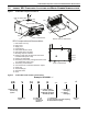
Liebert XDV Component Locations and Model Number Nomenclature 1.0 LIEBERT XDV COMPONENT LOCATIONS AND MODEL NUMBER NOMENCLATURE Figure 1 Liebert XDV component locations 2 3 Rear of Liebert XDV 13 15 14 7 Top of Liebert XDV 1 5 9 4 11 16 Front of Liebert XDV Bottom View of Liebert XDV XDV Components and Nomenclature 1. Removable Fan Tray 2. Return Line 3. Supply Line 4. Fan Switches 5. Removable Blocker Plates 6. Removable Rear Inlet Grille 7. Mounting Clips for Cabinets 8.
Installation 2.0 INSTALLATION 2.1 References This document must be used together with site specific documentation and documentation for other parts of the system. 2.2 Pre-Installation Checks • Verify that the Liebert XDV voltage matches the available utility power. The serial tag with this information is on the top of the unit, near the rear. • Check the received materials to be sure all required assemblies and parts have been received.
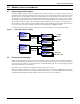
General product information 3.0 GENERAL PRODUCT INFORMATION 3.1 Product/System Description The Liebert XDV cooling system is designed to be attached to the top of a computer cabinet or rack containing heat dissipating equipment. Two fans draw hot air exhausted from the equipment or from the hot aisle, pass it through a cooling coil and discharge cool air back down to the cold aisle, where the equipment's air intake is located.
General product information 3.3 Equipment Inspection Upon arrival of the unit, and before unpacking, verify that the labeled equipment matches the bill of lading. Carefully inspect all items for either visible or concealed damage. Damage should be immediately reported to the carrier and a damage claim filed with a copy sent to Liebert Corporation or to your sales representative. ! CAUTION Risk of sudden refrigerant discharge. Can cause loss of charge and minor injury.
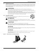
General product information 3.3.2 Unit Handling If possible, transport the unit using a forklift or pallet jack. • If using a forklift or pallet jack, ensure that the fork tine length is suitable to safely move the packaged unit. • Liebert Corporation recommends that the unit remain in the protective packaging until located at the installation site. • When handling and unpacking the unit, exercise great care to prevent damage. • Do not use unit piping to lift or move the Liebert XDV 3.3.
General product information Export Packaging 1. 2. 3. 4. Figure 6 Unbend all metal tabs as indicated in Step 1 in Figure 6. Remove outer packaging when ready to install the Liebert XDV. Keep the Liebert XDV covered by the unit bag until removal from pallet. Do not use unit piping to lift or move the Liebert XDV. Removing export shipping package Plastic bag used for shipping not shown for clarity.
General product information Removing the Liebert XDV from the Pallet 1. Unfold the unit bag to expose the Liebert XDV. 2. Verify the nameplate information found on the Liebert XDV against the bill of lading. If the information does not match the product specified, contact your local Liebert sales representative. 3. At least two properly trained personnel may lift the Liebert XDV off the pallet and onto a flat surface. 4.
Mechanical Considerations 4.0 MECHANICAL CONSIDERATIONS 4.1 Determining Placement in the Conditioned Space Liebert XDVs should be placed above or on top of the cabinets that generate the greatest amount of heat. If heat loads are dispersed evenly throughout the room, the Liebert XDV modules may be spread out accordingly. The Liebert XDV is engineered to fit atop computer enclosure cabinets. Figure 8, below, illustrates the unit’s dimensions and the location of pipes, the fan tray and power connections.
Mechanical Considerations 4.2 Changing the Air Intake Location The Liebert XDV comes from the factory with the air intake on the rear of the unit. If required for your application, this can be changed so that the Liebert XDV takes in heated air from the bottom. This is done more easily and safely before the unit is mounted on a computer cabinet. ! WARNING Risk of high-speed moving parts. Can cause death, injury and equipment damage.
Mounting the Liebert XDV 5.0 MOUNTING THE LIEBERT XDV The Liebert XDV module must be securely attached to the top of the computer cabinet or, alternatively, suspended above the cabinet. For mounting atop the computer cabinet, see 5.1 - Mounting the Liebert XDV on Top of the Cabinet; to hang the Liebert XDV above the computer cabinet, refer to 5.2 - Suspended Mounting Method. Be sure to follow all applicable codes. ! WARNING Risk of top-heavy cabinet falling. Can cause equipment damage, injury or death.
Mounting the Liebert XDV Figure 11 Mounting hole locations—standard mounting method Rear of Liebert XDV Front of Liebert XDV Bolt 1/4" - 20 (2 places, typ.) Fan tray removed to show mounting location(s) of 1/4" - 20 bolts Figure 12 Mounting hole locations—alternate mounting points Front of Liebert XDV 13/16" (21mm) A B 1 1 B 11" (279mm) 20-7/8" (530mm) 20-5/8" (524mm) A 1 A A Notes 1. These dimensions may be used when attaching Liebert XDV to a non-Liebert cabinet. 2.
Mounting the Liebert XDV 5.1.2 Using Supplied Clips for Mounting 1. Attach the mounting clips to the back of the Liebert XDV by fitting them into the machined slots. Tighten the bolts. 2. If your cabinet has mounting holes in position for the clips, align the Liebert XDV properly and insert the bolts from the bottom of the cabinet and secure them with the included lock washers and nuts (see Figure 13). Tighten the nuts. If your cabinet’s mounting holes do not match the clips, drill holes as required.
Mounting the Liebert XDV 5.2 Suspended Mounting Method The Liebert XDV also may be mounted above the cabinet by suspending it either from overhead components or from Unistruts above the cabinets (see Figures 15 and 16). An optional kit available from Liebert will simplify mounting the Liebert XDV above the computer cabinet. Each suspended-mounting method requires that the supporting components be strong enough to support the Liebert XDV’s weight with coolant, 79 lb. (36kg).
Mounting the Liebert XDV 5.2.1 Suspending the Liebert XDV from Unistruts The Liebert XDV may be bolted to customer-supplied Unistruts. The height of the Unistruts above the computer cabinet must be adequate to accommodate the combined height of the Liebert XDV and the baffle. To suspend the Liebert XDV from a Unistrut system: 1. Bolt the hangers to each corner of the Liebert XDV, inserting the Liebert-supplied bolts into factory-fabricated holes in the bottom of the Liebert XDV. See Figure 15. 2.
Mounting the Liebert XDV Figure 16 Suspending Liebert XDV from the overhead structure 3/8"-16 all-thread bolts, field-supplied, typical Hanging Liebert XDV unit To prevent bypass air from recirculating through the Liebert XDV without it passing through the cabinet, this space between the hanging XDV and the cabinet must be blocked.
Mounting the Liebert XDV 5.3 Mounting Liebert XDVs in Stacked Setup Liebert designed the Liebert XDV to permit mounting the units in a stacked arrangement to increase the system’s heat-removal. Stacking may be done either during the original system or added later to an existing configuration. Stacking Liebert XDVs is possible when suspending units from either Unistruts or from the overhead structure. Hanger brackets are available in two lengths to ease hanging Liebert XDVs in a stacked arrangement.
Mounting the Liebert XDV 5.3.1 Hanging Stacked Liebert XDVs from Unistruts Because the upper Liebert XDV in a stacked arrangement must be positioned farther forward than the lower Liebert XDV, two sets of Unistruts are required. The second set of Unistruts must be installed 9-7/8 inches (251mm) forward of the first set. This arrangement positions the stacked Liebert XDVs so that they meet the air-intake criteria shown in Figure 10 and Figure 17.
Mounting the Liebert XDV 5.3.2 Hanging Stacked Liebert XDVs from the Overhead Structure Because the upper Liebert XDV in a stacked arrangement must be positioned farther forward than the lower Liebert XDV, the place where the hangers attach to the overhead structure must be offset accordingly. The second row of attachment locations must be 9-7/8 inches (251mm) forward of the first row of hanger mounting locations.
Piping 6.0 PIPING 6.1 European Union Fluorinated Greenhouse Gas Requirements Stationary air conditioning, refrigeration, heat pump equipments and stationary fire protection systems in the European Community market and operating with fluorinated greenhouse gases (f-gas), such as R407C, R134a, R410A, must comply with the F-Gas Regulation: (EC) No. 842/2006 (F-gas). The regulation prohibits, among other actions, venting fluorinated greenhouse gases to the atmosphere.
Piping Figure 22 Typical Liebert XDV piping—non-interlaced connection TOP VIEW—NOT TO SCALE Return Supply Liebert XDP/LieLiebert XDV A 6.2.1 Liebert XDV A Liebert XDV A Liebert XDV A Piping Connections to Liebert XDP or Liebert XDC Refer to site specific drawings for general locations of the piping connections. For Liebert XDV connection locations, refer to Figures 1 and 24. 6.
Piping Figure 23 Hard-piped connection diagram Return Main (seen from end ) 2-1/8" O.D. or 2-5/8" O.D. Recommended Arc Acceptable Arc Supply Main (seen from end ) 1-1/8" O.D. or 1-3/8" O.D. 5/8” Refrigerant -Grade Full-Port Ball Valve Field-Supplied and Field-Installed 1/2” Refrigerant-Grade Full-Port Ball Valve Field-Supplied and Field- Installed Copper Tubing Total length of each line from Liebert XDV to Main; not to exceed 72" (1829mm) Refer to Table 4 for details.
Piping 6.4 Hard Piped Connection Sizes Supply piping connection is 1/2" OD copper pipe and return piping connection is 5/8" OD copper. 6.4.1 Holding Charge—Hard-Piped Units The Liebert XDV in hard-piped configuration is shipped with a low-pressure holding charge (about 30 psi) of nitrogen to prevent oxidation and moisture. This must be vented before removing the caps on the ends of the supply and return piping. To vent the holding charge: 1.
Piping Figure 25 Schrader valve location for venting holding charge Front of Liebert XDV Top of Liebert XDV Schrader Valve SCHRADER VALVE SUPP LY ( IN) RE TURN (OUT ) Supply pipe connection (1/2" OD) 6.4.2 Return pipe connection (5/8" OD) Rear of XDV Brazing Preparations—Hard-Piped Units After the holding charge for a hard-piped Liebert XDV has been vented, a torch can be used to remove the caps over the ends of the supply and return lines.
Piping Table 4 Branch piping sizes for refrigerant loop Pipe Function Size / Equivalent Pipe Length Liebert XDP/Liebert XDC supply line, from Liebert XDP/Liebert XDC supply to farthest Liebert XDV Liebert XDP/Liebert XDC return line, from farthest Liebert XDV to Liebert XDP/Liebert XDC return From Liebert XDV supply to supply line of Liebert XDP/Liebert XDC From Liebert XDV return to return line of Liebert XDP/Liebert XDC 6.6 1-1/8" OD (1.025" ID) for lengths up to 60 feet (18m) 1-3/8" OD (1.
Piping 6.6.1 Refrigerant Charge—Pre-Charged Option Liebert XDVs with the pre-charged option are equipped with one-shot connections on the supply and return fittings. These contain a charge of R-134a refrigerant under pressure within the unit. This charge must not be vented. Do not remove the pipe caps or plugs before the unit is ready for connection to Liebert XD Piping. Do not disconnect one-shot connections after they have been connected. 6.
Piping 6.9 Connecting a Liebert XDV with Liebert Flex Pipe to an Operational Liebert XD System NOTICE Before connecting the Liebert XDV with Liebert Flex Pipe to the prefabricated piping mains, check the whole system for leaks. Check the Liebert XDV to ensure that the unit has no refrigerant leaks. Read all instructions before beginning installation.
Piping Figure 29 Detail view of Liebert XD Flex Pipe and prefabricated piping port Supply Side Torque Range for 1/2" coupler is 22.1 to 25.8 lb/ft (30-35Nm) Return Side Torque Range for 1" coupler is 59 to 62.7 lb/ft (80-85Nm) Tighten collar with wrench. DO NOT OVERTIGHTEN! Service Valve Note: Make sure the valve is closed before attaching flex pipe to the system. Hold threaded coupler here with a wrench to keep the pipe stationary while tightening collar with another wrench. Flex Pipe 8.
Piping 6.10 Disconnecting a Liebert XDV With Liebert Flex Pipe From a Liebert XD System ! CAUTION Risk of sudden discharge of pressurized refrigerant. Can cause equipment damage or injury. Do not disconnect threaded refrigerant couplers at the unit cabinet end without relieving system pressure. Reclaim any refrigerant during removal of unit from system.
Piping Figure 32 Piping mains without Liebert XDV and Liebert Flex Pipe 11. Repeat Steps 8 through 10 for the return coupler (larger coupler). 12. Carefully lay the Liebert Flex Pipe on the top of the Liebert XDV. NOTICE Risk of permanent damage to the flex pipes. Do not fold or bend flex pipe tightly. 13. Carefully unbolt the Liebert XDV from the cabinet or hanging bracket, if applicable. 14.
Electrical 7.0 ELECTRICAL The unit must be installed in accordance with national wiring regulations. Refer to the unit’s serial tag for electrical requirements. Refer to Table 5 for details. Replacement of any wiring or supply cord must be performed only by the manufacturer, the manufacturer’s service agent or a similarly qualified person. 7.1 Connecting High Voltage Cables for CSA/C-US Certified Units ! WARNING Risk of electric shock. Can cause injury or death.
Electrical Figure 34 Liebert XDV electrical connections for CE-approved units 60Hz MODELS ONLY. FIELD WIRING CONNECTIONS AT TERMINAL STRIP TO BE N.E.C. CLASS 2 USE SWITCH CONTACTS WITH 75 V.A. MINIMUM 50Hz MODELS ONLY. FIELD WIRING CONNECTIONS AT TERMINAL STRIP FOR SAFETY EXTRA LOW VOLTAGE CIRCUITS ONLY. USE SWITCH CONTACTS RATED 75 V.A. MINIMUM, 24 VOLTS AC MAXIMUM.
Electrical 7.2 Connecting Low Voltage Wiring—Optional Low voltage connections to the Liebert XDV are available only on units with the optional condensate detection feature. The low voltage connections are on the right side of the electrical connections box, just above the power connections (see Figure 35). These dry contacts can to be connected to a monitoring unit, such as Liebert’s SiteScan®. For units equipped with condensate detection, make low voltage connections according to site-specific drawings.
Installation Checklist and System Fill for Startup 8.0 INSTALLATION CHECKLIST AND SYSTEM FILL FOR STARTUP 8.1 Checklist for Proper Installation ___ 1. Liebert XDV module is properly mounted, secured either to the cabinet, overhead structure or to the Unistruts. ___ 2. Power cords connected to electrical supply. ___ 3. Low voltage wiring to optional condensate detection on Liebert XDV. ___ 4. Piping from Liebert XDP to Liebert XDV, with isolation valves piped to each Liebert XDV. a.
Operation 9.0 OPERATION The Liebert XDV’s fan controls are on the front of the unit, near the fans, for easy access. Each switch controls the operation of one fan (see Figure 36). The separate switches permit the use of only one fan at a time, reducing the airflow if the Liebert XDV’s full cooling capacity is not needed. The Liebert XDV’s primary and secondary circuit breakers are also on the front of the unit. They are at the top left when facing the Liebert XDV (see Figure 36).
Maintenance 10.0 MAINTENANCE Minimal maintenance is required to keep the Liebert XDV operating at optimal levels. The unit should be cleaned and checked for damage and worn parts. Suggested maintenance includes: • Cooling fins—Clean any dust and debris from the cooling fins, taking care not to bend them • Circulating fans—Clean any dust from the fans. 10.
Maintenance 10.2.1 Accessing Internal Electrical Components 1. Disconnect all power inputs. 2. Remove five screws to remove the front electrical panel cover. SeeFigure 37 and 12 of 13 3. Lift off the panel.
Maintenance To remove the fan tray: 1. Remove the front electrical panel cover as described in 10.2.1 - Accessing Internal Electrical Components. 2. Disconnect the 12-pin connector. Take care not to stretch or stress the electrical wires to the fans. 3. Remove the four screws holding the fan tray on the Liebert XDV. 4. Support the fan tray when removing the last screw to keep it from falling. 5. Set the screws aside for reinsertion after maintenance is completed. 6.
Specifications 11.
Specifications Table 6 Liebert XDV8 specifications Models 60 Hz 60 Hz 50 Hz Nominal (98°F [37°C] EAT): 8.8kW / 2.5 Tons Maximum (95°F [35°C] EAT): 8.8kW / 2.
Specifications Table 7 Liebert XD Liebert Flex Pipe assemblies, supply and return Description Liebert XD Flex Pipe Kit Liebert P/N Straight Connection Assembly Liebert P/N 90-Degree Connection Assembly 186568G1 186567G1 6 (1.8) 186568G2 186567G2 10 (3.0) 186568G3 186567G3 8 (2.5) 186568G4 186567G4 4 (1.
Ensuring The High Availability Of Mission-Critical Data And Applications. Emerson Network Power, the global leader in enabling business-critical continuity, ensures network resiliency and adaptability through a family of technologies—including Liebert power and cooling technologies—that protect and support business-critical systems. Liebert solutions employ an adaptive architecture that responds to changes in criticality, density and capacity.