POWER AVAILABILITY GXT2-6000RT230™ & GXT2-4500RT230™ USER MANUAL 230VAC
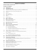
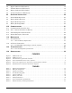
TABLE OF CONTENTS IMPORTANT SAFETY INSTRUCTIONS . . . . . . . . . . . . . . . . . . . . . . . . . . . . . . . . . . . . . . . . . . . . . . . .1 GLOSSARY OF SYMBOLS . . . . . . . . . . . . . . . . . . . . . . . . . . . . . . . . . . . . . . . . . . . . . . . . . . . . . . .2 1.0 INTRODUCTION . . . . . . . . . . . . . . . . . . . . . . . . . . . . . . . . . . . . . . . . . . . . . . . . . . . . . . . . . .3 2.0 SYSTEM DESCRIPTION . . . . . . . . . . . . . . . . . . . . . . . . . . . . . . . . . . . . . .
8.6 Bypass Indicator LED (Amber) . . . . . . . . . . . . . . . . . . . . . . . . . . . . . . . . . . . . . . . . . . . . . . . . 19 8.7 UPS ON Indicator LED (Green) . . . . . . . . . . . . . . . . . . . . . . . . . . . . . . . . . . . . . . . . . . . . . . . 19 8.8 Battery Indicator LED (Amber). . . . . . . . . . . . . . . . . . . . . . . . . . . . . . . . . . . . . . . . . . . . . . . . 19 8.9 AC Input Indicator LED (Green) . . . . . . . . . . . . . . . . . . . . . . . . . . . . . . . . . . . . . .
IMPORTANT SAFETY INSTRUCTIONS SAVE THESE INSTRUCTIONS This Manual Contains Important Safety Instructions. Read all safety and operating instructions before operating the Uninterruptible Power Supply (UPS). Adhere to all warnings on the unit and in this manual. Follow all operating and user instructions. This equipment can be operated by individuals without previous training. This product is designed for Commercial/Industrial use only.
GLOSSARY OF SYMBOLS Risk of electrical shock ! Indicates caution followed by important instructions AC input AC output i - Requests the user to consult the manual + Indicates the unit contains a valve-regulated lead acid battery PbH2SO4 R Recycle DC voltage Equipment grounding conductor Bonded to ground AC voltage ON/Alarm Silence/Battery Test OFF/Bypass Indicates the position of a fuse 2
Introduction 1.0 INTRODUCTION Congratulations on your choice of the Liebert UPStation GXT2-6000RT230 and GXT2-4500RT230 Uninterruptible Power System (UPS). It provides conditioned power to microcomputers and other sensitive electronic equipment. Upon generation, AC power is clean and stable. However, during transmission and distribution it may be subject to voltage sags, spikes, or complete power failure that may interrupt computer operations, cause data loss, or even damage equipment.
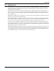
System Description 2.0 SYSTEM DESCRIPTION Input L1 Output Dynamic Bypass TVSS & EMI/RFI Filters N L1 Rectifier /PFC DC-to-DC Converter Battery Charger Inverter N Battery G 2.1 G Transient Voltage Surge Suppression (TVSS) and EMI/RFI Filters These UPS components provide surge protection and filter both electromagnetic interference (EMI) and radio frequency interference (RFI). They minimize any surges or interference present in the mains line and keep the sensitive equipment protected. 2.
System Description 2.5 DC-to-DC Converter The DC to DC converter utilizes energy from the battery system and raises the DC voltage to the optimum operating voltage for the inverter. This allows the inverter to operate continuously at its optimum efficiency and voltage, thus increasing reliability. 2.6 Battery The UPStation GXT2 utilizes valve-regulated, nonspillable, lead acid batteries. To maintain battery design life, operate the UPS in an ambient temperature of 20°C to 25°C (68°F to 77°F).
Major Components 3.0 MAJOR COMPONENTS The GXT2 is composed of three major assemblies to provide easier handling, installation, and versatility. 3.1 Main Frame and Electronics This 5U cabinet is shipped with internal batteries installed and a basic, hardwire distribution box attached and ready to install.
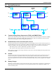
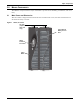
Major Components Figure 2 GXT2, rear view Battery Disconnect External Battery Connector Fans UPS Output Circuit Breaker DB-9 Communication Port REPO Connector Relay Card Slot Removable Power Distribution Box Serial Card Slot (SNMP, OCWEB, USB) 3.2 Internal Battery Packs The UPS has two internal battery packs behind a battery access door on the front of the unit. Each pack is fitted with a connector to link to the UPS.
Major Components 3.3 Removable Power Distribution Box The UPS arrives with a basic hardwire power distribution pack installed. This box always contains the UPS input circuit breaker. Optional versions may be available to replace the standard box for custom installations.
What’s Included 4.0 WHAT’S INCLUDED The GXT2 are shipped with the following items: • • • • • • • • • • GXT2-6000RT230 and GXT2-4500RT230 user manual Vertical display overlay Top bezels - 2 MultiLink software CD MultiLink serial cable, 10 ft (3m) Rack mount handles Support base - 2 Mounting hardware Configuration program disk DB9 port cover Top bezels (tower use) MultiLink software CD Vertical display overlay Rack mount handles MultiLink serial cable 10 ft (3m) www.liebert.
Installation and Configuration 5.0 INSTALLATION AND CONFIGURATION Do NOT attempt to start the UPS, turn on any circuit breaker or energize the input power until instructed to do so in 6.0 - Initial Start-Up and Electrical Checks. Visually inspect the UPS for freight damage. Report any damage to the carrier and your local dealer or Liebert representative. ! CAUTION The UPS is heavy (see 13.0 - Specifications). Take proper precautions when lifting or moving it.
Installation and Configuration 5.1.3 Installing the Adjustable Rack-Mount Kit—Sold Separately This kit contains parts needed to mount several different models of UPS and external battery cabinets into EIA310-D standard four-post racks that are 18-32" deep (457-813mm). The weight limit per pair of adjustable rack-mounting brackets is 91 kg (200lbs.).
Installation and Configuration 4. Get eight (8) M4 screws and eight (8) M4 nuts from the hardware pack in this kit. Each nut has a locking, nylon insert that begins gripping the screw when it is halfway tight. Make sure to tighten the nut and screw completely to ensure locking action. Fasten the rear member and the front member together using (4) screws and (4) nuts per bracket assembly as shown in at right.
Installation and Configuration 5.2 External Battery Cabinet Installation Optional Liebert external battery cabinets may be connected to the UPS to provide additional battery run time. External battery cabinets are designed to be placed on one side of the UPS or stacked beneath the UPS. ! CAUTION The external battery cabinet(s) are heavy (see 13.0 - Specifications). External battery cabinets can be used in rack-mount or tower configuration. Take proper precautions when lifting them. 1.
Installation and Configuration 5.3 Connect the Internal Batteries Using the External Connector The internal connectors of the internal battery packs will be connected when shipped. However, the internal batteries will be disconnected from the UPS using a rear panel connector. The connector attaches to the UPS in both the open and closed position using two screws. The picture on the left shows the connector in the open position, as shipped.
Installation and Configuration Figure 6 Distribution box electrical connections diagram PD-CEHDWR Mains PD-CEHDWRBYP 32A External Branch CB Input Mains Input Input CB 32A External Branch CB Output 30 30 Input CB 30 UPS - PFC, Battery, Inverter Output Inv. 30 UPS Output CB Byp. UPS Output CB UPS - PFC, Battery, Inverter PD-CEHDWR and PD-CEHDWRBYP Terminal Block Connections Conduit entry holes are provided on the rear and side of the box.
Initial Start-Up and Electrical Checks 6.0 INITIAL START-UP AND ELECTRICAL CHECKS 1. 2. 3. 4. 5. 6. 7. 8. 9. 10. 11. 12. 13. 14. Verify that the Input Output circuit breakers are off. During initial system checks, disconnect all loads (open load disconnects). Inspect all wiring, cables, and connection. If external battery cabinets are used, verify that the battery interconnect cables are fully inserted in the sockets.
Configuration Program 7.0 CONFIGURATION PROGRAM The final step of installation may require custom configuration of your UPS using the enclosed configuration program. Some configuration settings may be changed only while the UPS is off. These should be set before the UPS is put into full-time service powering the critical load. For most users operating with 230VAC and with no external batteries, the factory default settings will be adequate. 7.
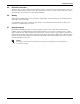
Controls and Indicators 8.0 CONTROLS AND INDICATORS All indicators illuminated for illustration only. UPStation GXT AC INPUT 8.1 BATTERY UPS ON BYPASS ON/Alarm Silence/Manual Battery Test Button This button controls output power to connected load(s) and has three functions: • ON • Alarm Silence • Manual Battery Test ON - Pressing this button will start up the UPS in order to provide conditioned and protected power. Alarm Silence - To silence alarms, press this button for at least one Second.
Controls and Indicators 8.3 Load Level Indicators (4 Green, 1 Amber) The load level indicators display the approximate electrical load placed upon the UPS at all times. 8.4 Battery Level Indicators (5 Green) The battery level indicators display approximate battery capacity at all times. The UPStation GXT2 is equipped with automatic and remote battery test features. The automatic test occurs every 14 days (this option is user configurable) if mains has not been interrupted.
Operating Instructions 9.0 OPERATING INSTRUCTIONS 9.1 Normal Mode Operation During normal operation, mains power provides energy to the UPS. The filters, power factor correction circuit and the inverter process this power to provide computer grade power to connected loads. The UPS maintains the batteries in a fully charged state. The four green load level LEDs indicate an approximate level of load in 25% increments.
Communications 10.0 COMMUNICATIONS 10.1 Communications Interface Port The UPStation GXT2 UPS has a standard DB-9 serial port female connector located on the rear of the UPS unit.
Communications 10.3 UPS Intelligent Communications The UPStation GXT2 is equipped with two Intellislot® ports to provide advanced communication and monitoring options. The Intellislot port closer to the corner of the UPS chassis is the serial card slot. This Intellislot port is used for the OCWEBCARD and the USBCARD. The other Intellislot port is used for RELAYCARD-INT or the MULTIPORT Card.
Communications 10.4 Remote Emergency Power Off The UPS is equipped with a Remote Emergency Power Off (REPO) connector. The user must supply a means of interfacing with the REPO circuit to allow disconnecting the UPS input feeder breaker to remove all sources of power to the UPS and connected equipment to comply with national and local wiring codes and regulations.
Maintenance 11.0 MAINTENANCE 11.1 Internal Battery The UPStation GXT2 requires very little maintenance. The batteries are valve-regulated, non-spillable, flame retardant, lead acid, and should be kept charged to obtain their designed life. The UPS continuously charges the batteries when connected to the mains supply. When storing the UPS for any length of time, it is essential to plug the UPS in for at least 24 hours every four to six months to ensure full recharge of the batteries.
Maintenance 11.1.1 Internal Battery Replacement ! CAUTION A battery can present a risk of electrical shock and high short circuit current. Observe the following precautions before replacing the batteries: • • • • Remove rings, watches and other metal objects. Use a Phillips (cross-head) screwdriver with insulated grips. Do not lay tools or other metal objects on top of the batteries.
Maintenance 11.2 AC Power Connections Power connections may be disconnected from the UPS cabinet via a removable distribution box. This may be a convenient feature if the UPS must be moved a short distance or replaced. This box allows power connections to be conveniently disconnection from the main UPS cabinet. A label is attached to the UPS to describe these procedures.
Troubleshooting 12.0 TROUBLESHOOTING The information below indicates various symptoms a user may encounter in the event the UPStation GXT2 develops a problem. Use this information to determine whether external factors caused the problem and how to remedy the situation. 1. 1. The Fault indicator will illuminate, indicating the UPS detected a problem. 2. 2. An alarm will sound, alerting that the UPS requires attention.
Troubleshooting Table 4 Troubleshooting guide Problem Cause Solution Ensure UPS is OFF. Disconnect all loads and ensure nothing is lodged in output receptacles. Ensure loads are not defective or shorted internally. UPS is operating from battery mode, make certain UPS is UPS not plugged in. securely plugged into the wall receptacle. UPS input protection fuse UPS is operating from battery mode. Save data and close Battery indicator LED is has blown/opened. applications.
Troubleshooting Table 4 Troubleshooting guide (cont’d) Problem Cause Solution Fault and LEDs D&E are Illuminated Charger malfunction Battery LED is flashing. Battery source is not available; continuous horn. Table 5 If the charger is overvoltage, the UPS will shutdown. If the charger is undervoltage and the batteries are nearly depleted, this alarm will give a temporary warning before the UPS shuts down. UPS requires service.
Troubleshooting Table 6 Battery run times Internal Battery (minutes) Internal Battery + 1 External Battery Cabinet (minutes) Internal Battery + 2 External Battery Cabinets (minutes) Internal Battery + 3 External Battery Cabinets (minutes) Internal Battery + 4 External Battery Cabinets (minutes) Load% 10% 20% 30% 40% 50% 60% 70% 80% 90% 100% 10% 20% 30% 40% 50% 60% 70% 80% 90% 100% 10% 20% 30% 40% 50% 60% 70% 80% 90% 100% 10% 20% 30% 40% 50% 60% 70% 80% 90% 100% 10% 20% 30% 40% 50% 60% 70% 80% 90% 10
Troubleshooting 12.0.1 Auto-Learning Battery Run Times As batteries age, the estimated runtimes may become less accurate. The GXT2 is programmed to “learn” from a full battery discharge and modify the estimated runtime for the measured battery capacity. This can improve accuracy and compensate for aging batteries or batteries that operate at different ambient temperatures. The UPS will update the anticipated run time calculation only under certain conditions.
Specifications 13.0 SPECIFICATIONS Table 7 UPS specifications Model Number Model Rating Dimensions mm (in.) Unit, W x D x H Shipping, W x D x H Weight kg (lbs) Unit Shipping Input AC Parameters Nominal Operating Frequency Factory Default VAC GXT2-6000RT230 6KVA / 4,200W 221 x 547 x 430 (8.7 x 21.5 x 16.9) 560 x 690 x 500 (22.05 x 27.17 x 19.7) 67 (151) 79.5 (175.3) Audible Noise 67 (151) 79.5 (175.
Specifications Table 8 Power distribution specifications Model Number PD-CEHDWR PD-CEHDWRBYP Amps Rating 32 Amps Input Power Connection 3-Wire Hardwired, 6-10mm2 (8-10AWG) Output Power Connection 3-Wire Hardwired, 6-10mm2 (8-10AWG) Includes: Two IEC320 C19 16A/250V sockets Input Branch Circuit Breaker Table 9 Two IEC320 C19 16A/250V sockets Manual Bypass Switch with Indicator Lamps 32A, Supplied by User External battery cabinet specifications Model Number GXT2-240VBATT Used w/ UPS model
Specifications 34
POWER AVAILABILITY GXT2-6000RT230™ & GXT2-4500RT230™ USER MANUAL The Company Behind the Products With over a million installations around the globe, Liebert is the world leader in computer protection systems.