AC Power For Business-Critical Continuity™ Liebert® GXT3-10000T220™ User Manual, 10kVA, 50/60 Hz, 120/208/220V
TABLE OF CONTENTS IMPORTANT SAFETY INSTRUCTIONS . . . . . . . . . . . . . . . . . . . . . . . . . . . . . . . . . . . . . . . . . . . . . . . .1 1.0 INTRODUCTION AND SYSTEM DESCRIPTION . . . . . . . . . . . . . . . . . . . . . . . . . . . . . . . . . . . . .4 1.1 Device Overview . . . . . . . . . . . . . . . . . . . . . . . . . . . . . . . . . . . . . . . . . . . . . . . . . . . . . . . . . . . . . 5 2.0 UNPACKING THE UPS AND SITE PREPARATION . . . . . . . . . . . . . . . . . . . . . . . . . . . . . .
5.0 MAINTENANCE . . . . . . . . . . . . . . . . . . . . . . . . . . . . . . . . . . . . . . . . . . . . . . . . . . . . . . . . . 20 5.1 Test, Replacement and Disposal of Batteries . . . . . . . . . . . . . . . . . . . . . . . . . . . . . . . . . . . . . 20 5.2 Storage . . . . . . . . . . . . . . . . . . . . . . . . . . . . . . . . . . . . . . . . . . . . . . . . . . . . . . . . . . . . . . . . . . . 20 5.3 Cleaning . . . . . . . . . . . . . . . . . . . . . . . . . . . . . . . . . . . . . . . . . . .
IMPORTANT SAFETY INSTRUCTIONS SAVE THESE INSTRUCTIONS This manual contains important safety instructions. Read all safety and operating instructions before operating the uninterruptible power system (UPS). Adhere to all warnings on the unit and in this manual. Follow all operating and user instructions. This equipment must be operated only by individuals who are properly trained and qualified. This product is designed for commercial/industrial use only.
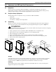
! WARNING Although the Liebert GXT3 has been designed and manufactured to ensure safety, improper use can result in electrical shock or fire. To ensure safety, observe the following precautions: ® ™ • Turn Off and isolate the Liebert GXT3 before cleaning it. Use only a soft cloth; never use liquid or aerosol cleaners. • Never block or insert any objects into the ventilation holes or other openings of the UPS. • Do not place the Liebert GXT3 power cord where it might be damaged.
Leakage Current ! WARNING Connect the ground (earth) safety conductor before connecting any other cables. ELECTROMAGNETIC COMPATIBILITY—The Liebert® GXT3™ complies with the limits for a Class A Digital Device, Pursuant to Part 15 of FCC rules. Operation is subject to the following conditions: • This device may not cause harmful interference • This device must accept any interference received, including interference that may cause undesired operation.
Introduction and System Description 1.0 INTRODUCTION AND SYSTEM DESCRIPTION Congratulations on your choice of the Liebert® GXT3™-10000T220 UPS. It provides conditioned power to microcomputers and other sensitive electronic equipment. When generated, AC power is clean and stable. However, during transmission and distribution it is subject to voltage sags, spikes and complete power failure that may interrupt computer operations, cause data loss and damage equipment.
Introduction and System Description 1.
Unpacking the UPS and Site Preparation 2.0 UNPACKING THE UPS AND SITE PREPARATION 2.1 Inspection Upon receiving your Liebert® GXT3-10000T220™, examine the packaging for any signs of mishandling or damage. While removing shipping materials, inspect the UPS for damage. If any damage is noted, notify your local Liebert representative and your carrier. 2.
Unpacking the UPS and Site Preparation 2.4 Environmental Conditions Install the Liebert® GXT3™ indoors in a controlled environment where it cannot be accidentally turned off. Place it on a level, even surface in an area with unrestricted airflow around the unit. The installation location must be free of water, flammable liquids, gases, corrosives and other conductive contaminants. Maintain a minimum clearance of 100mm (4 inches) in the front and rear of the UPS.
Installation 3.0 INSTALLATION 3.1 Electrical preparations Before beginning installation, the input source must be isolated and locked out to prevent connection during installation. The input circuit breaker on the rear of the UPS must be in the Off position. ! WARNING Installation may be carried out only by qualified technicians and in conformity with the applicable safety standards.
Installation 3.4 External Electrical Connections The external electrical connections may be accessed by removing the protective panel on the rear of the UPS (see Figure 2) (panel ships loose from factory). Select a conduit knockout appropriate for your cabling, based on local electrical codes. ! WARNING Before removing electric protective panel, ensure that the UPS is isolated.
Installation Figure 6 Dual source input supply—input and output connections UPS Input ~ BYP L1 L2 Bypass Input ~ L1 L2 Output ~ GET X1 X2 X3 X4 120 UPS Feed 208 220 Bypass Feed 240 Figure 7 120 0 Hardwire terminals Jumper removed for clarity 3.6.1 Input and Output Connection Requirements • Any 120V loads must be distributed evenly between X1-X2, X1-X4 and X4-X2. Do not connect loads between X3-X2 or between X3-X4—these are not standard voltages.
Installation 3.7 Connecting Power Cables 1. 2. 3. 4. 5. 6. • Open the UPS input breaker. Open the UPS bypass breaker. Set the maintenance breaker to the Bypass position. Remove the electrical connection protective panel, if installed, from the rear UPS panel. Connect loads to the output terminals as illustrated in Figure 7. Connect the utility to the corresponding input terminals (see Figure 7).
Operation 4.0 OPERATION 4.
Operation 4.2 Control Panel The Control Panel’s LCD and buttons are used to initiate various UPS operations, tests and commands and to view the status of the UPS. By pressing the Menu Up or Menu Down and Enter keys , it is possible to scroll through the various menus. For details, see 4.2.1 - Controls and Messages and Figure 11. Figure 10 Control Panel Fault LED Battery LED UPS On LED Bypass LED LCD Escape key Enter key Menu Up key 4.2.
Operation Figure 11 Menu tree Turn UPS On/Off Alarm Control Battery Test Battery Test Battery Test Contrast Set Battery Test Control Status Audible Alarm Start Window Parallel Menu Output Voltage Battery Pack System Status Main Setup Battery Test Interval DC Start UPS Address Parallel Model Tag Number Language Event Log Log Clear Types About IP Version 14
Operation Table 3 Displayed text—system block and main menu Item # and Name Status Menu Description Measure value Unit Output Volt V Output Freq 0.1Hz Output Current A Output Watt W Output VA VA Output Load % Input Volt V L2 Input Volt N/A L3 Input Volt N/A Input Freq 0.
Operation Table 3 Displayed text—system block and main menu (continued) Item # and Name Description Turn UPS ON/OFF Turn UPS to ONLINE Turn UPS to BYPASS Turn UPS to shutdown Turn UPS to no output Alarm control Control Menu Alarm ON Alarm OFF Batt Test Batt Test Cancel Battery Test Battery Test Report Contrast Darker Lighter Battery Test Report Test in progress Test to Low-Battery Test OK! Cancel Battery test Test fail Battery Test report Test stop by user Test unknown 1.
Operation 4.2.4 Fault Indicators If a fault occurs, the UPS automatically switches to BYPASS mode, ONLY in case of a battery disconnect fault will the original operating mode be maintained. The fault message alternates with UPS mode once a second, the red Fault LED illuminates on the control panel and the buzzer sounds continuously. If a fault occurs, proceed as follows: Buzzer alarm operation—The buzzer alarm can be switched On or Off.
Operation 4.3 Initial UPS Startup Procedure 1. 2. 3. 4. 5. 6. 7. 8. Inspect all power connections to ensure they are correct and secure. Open external circuit breakers/fused disconnects to the connected loads. Close all upstream circuit breakers and fused disconnects. Use a voltmeter to verify proper input voltage is present on the UPS and Bypass input terminals. See Table 9 for the range. Close the input breakers on the rear panel of the UPS (UPS input and Bypass input).
Operation 4.6 Return from Maintenance Bypass 1. Ensure all switches and circuit breakers upstream of the UPS are closed. 2. Ensure that both input circuit breakers are in the On position. 3. Turn the Maintenance breaker from BYPASS to UPS and replace the cover. The load now is supplied via electronic bypass. 4. Press the Menu button, select Control and press the Enter key . 5. Select Turn UPS On/Off and press the Enter key . The LCD displays Turn UPS to ONLINE. 6.
Maintenance 5.0 MAINTENANCE 5.1 Test, Replacement and Disposal of Batteries The Liebert® GXT3™ is designed to allow the user to replace the internal battery pack safely.
Communication 6.0 COMMUNICATION 6.1 Communication Interface Port The Liebert® GXT3™ UPS has a terminal block on the rear of the UPS unit. Several signals are provided on this port and are assigned as follows. 6.2 Dry Contact The Dry Contact includes eight pins, as shown and defined in Figure 12. Figure 12 Dry contact pin layout 1 2 (Low Battery Warning) 3 (Any Mode Shutdown) (On- Battery Warning) 6.2.
Communication 6.2.2 Battery Mode Shutdown Battery Mode Shutdown permits shutting down the UPS by turning off the rectifier, inverter and static switch so that there is no power to the load when the UPS is On Battery. The auxiliary power for the UPS will still be active. Battery Mode Shutdown can be performed locally or remotely: • Local Battery Mode shutdown can be performed by shorting the pins in Set 4.
Communication 6.3.1 Liebert® MultiLink® Liebert MultiLink continually monitors the UPS and can shut down your computer or server in the event of an extended power failure. Liebert MultiLink can also be configured for use without the USB cable when the Liebert IntelliSlot® SNMP/Web card is installed in the UPS. Additionally, Liebert MultiLink can be configured to coordinate shutdown across the network with other computers running Liebert MultiLink when you purchase a Liebert MultiLink License Kit.
Troubleshooting 7.
Specifications 8.0 SPECIFICATIONS Table 9 Liebert® GXT3™ specifications 10,000 (9000) Model Rating, VA (W) Dimensions, in.
Specifications Table 10 Battery cabinet specifications GXT3-240TBATTCE Model Number Dimensions, W x D x H, in. (mm) Unit 31.5 x 11.81 x 26.57 (800 x 300 x 675) Shipping 41.8 x 16.
Product Warranty Registration 9.0 PRODUCT WARRANTY REGISTRATION To register for warranty protection: • Visit the Quick Links section of Liebert’s Web site at: http://www.liebert.com • Click on Product Warranty Registration and fill in the form. If you have any questions, please contact us at: • US: 800-222-5877 • Outside the US: 614-841-6755 liebert.upstech@emerson.
Ensuring The High Availability Of Mission-Critical Data And Applications. Emerson Network Power, a business of Emerson (NYSE:EMR), is the global leader in enabling Business-Critical Continuity™ from grid to chip for telecommunication networks, data centers, health care and industrial facilities.