
Owners manual
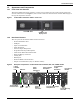
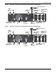
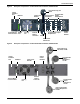
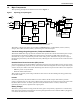
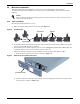
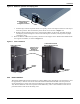

Table Of Contents
- Important Safety Precautions
- Save These Instructions
- Glossary of Symbols
- 1.0 Product Description
- 1.1 Features
- 1.2 Available Models
- 1.3 Appearance and Components
- 1.3.1 Front Panel and Controls
- 1.3.2 Rear Panel Features
- Figure 2 Rear panel components—Liebert GXT4 120V rack/tower, 500, 700, 1000VA model
- Figure 3 Rear panel components—Liebert GXT4 120V rack/tower, 1500VA model
- Figure 4 Rear panel components—Liebert GXT4 120V rack/tower, 2000VA model
- Figure 5 Rear panel components—Liebert GXT4 120V rack/tower, 3000VA model
- Figure 6 Rear panel components—Liebert GXT4 208V rack/tower, 3000VA model
- 1.4 Major Components
- 1.5 Operating Mode
- 2.0 Installation
- 3.0 Operation and Display Panel
- Figure 14 Operation and display panel
- 3.1 LED Indicators
- 3.2 Control Buttons
- 3.3 LCD
- 3.4 Menu Structure
- Figure 15 Menu structure
- 3.4.1 Startup Screen
- 3.4.2 Default Screen
- 3.4.3 Main Menu Screen
- 3.4.4 Prompt List
- 3.4.5 Warning List
- 3.4.6 Fault List
- 4.0 Operation
- 5.0 Communication
- 6.0 Maintenance
- 7.0 Troubleshooting
- 8.0 Battery Cabinet
- 9.0 Specifications
- Table 13 Specifications of GXT4-500RT120 - GXT4-700RT120 and GXT4-1000RT120 models
- Table 14 Specifications of GXT4-1500RT120 - GXT4-3000RT120 and GXT4-3000RT208 models
- Table 15 Battery cabinet specifications
- Table 16 Operating temperature parameters
- Table 17 Battery run times
- 9.1 Product Warranty Registration
- 9.2 Technical Support

Product Description
Liebert
®
GXT4
™
8
1.4 Major Components
The operating principle of the UPS is illustrated in Figure 7.
Figure 7 Operating principle diagram
The UPS is composed of utility input, TVSS and EMI/RFI filters, rectifier/PFC, inverter, battery
charger, DC-to-DC converter, battery, dynamic bypass and UPS output.
Transient Voltage Surge Suppression (TVSS) and EMI/RFI Filters
The Liebert GXT4 has surge protection and filters that protect the connected load from power surges,
electromagnetic interference (EMI) and radio frequency interference (RFI). These features can
minimize any surges or interference present in the utility power. The filters also prevent surges or
interference generated by the UPS from adversely affecting devices connected on the same branch as
the UPS.
Rectifier/Power Factor Correction (PFC) Circuit
In normal operation, the Liebert GXT4’s rectifier/power factor correction (PFC) circuit converts utility
power to regulated DC power for use by the inverter while ensuring that the wave shape of the input
current used by the UPS is near ideal. Extracting this sinewave input current achieves two objectives:
• Efficient power use by the UPS
• Reduced reflected harmonics
This results in cleaner power being available to other devices in the building not being protected by
the Liebert GXT4.
Inverter
In normal operation, the Liebert GXT4’s inverter utilizes the DC output of the PFC to produce
precise, regulated sine wave AC power. When utility power fails, the inverter receives DC power from
the DC-to-DC Converter. In either operation mode, the UPS inverter is online, continuously
generating clean, precise, regulated AC output power.
Battery Charger
The battery charger utilizes energy from the utility power and precisely regulates it to continuously
float charge the batteries. The batteries are being charged whenever the Liebert GXT4 is plugged in,
even when the UPS is not turned On.
TVSS
EMI/RFI
Input
Filter
Inverter
DC-DC
Converter
Battery
Charger
Battery
Dynamic
Bypass
L
G
N/L2*
G
L
Programmable
Outlet
Group 1
General
Outlet
Group
Programmable
Outlet
Group 2
General
Outlet
(3000 VA Only)
N/L2*
EMI/RFI
Output
Filter
* NOTE: ONLY the GXT4-3000 RT208 model (208V) requires L 2 (L6-20P).
All other models covered in this manual are 120 V L-N wired
Rectifier/
PFC