
Owners manual
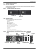
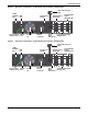
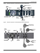
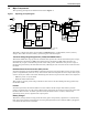
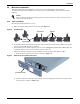
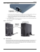

Table Of Contents
- Important Safety Precautions
- Save These Instructions
- Glossary of Symbols
- 1.0 Product Description
- 1.1 Features
- 1.2 Available Models
- 1.3 Appearance and Components
- 1.3.1 Front Panel and Controls
- 1.3.2 Rear Panel Features
- Figure 2 Rear panel components—Liebert GXT4 120V rack/tower, 500, 700, 1000VA model
- Figure 3 Rear panel components—Liebert GXT4 120V rack/tower, 1500VA model
- Figure 4 Rear panel components—Liebert GXT4 120V rack/tower, 2000VA model
- Figure 5 Rear panel components—Liebert GXT4 120V rack/tower, 3000VA model
- Figure 6 Rear panel components—Liebert GXT4 208V rack/tower, 3000VA model
- 1.4 Major Components
- 1.5 Operating Mode
- 2.0 Installation
- 3.0 Operation and Display Panel
- Figure 14 Operation and display panel
- 3.1 LED Indicators
- 3.2 Control Buttons
- 3.3 LCD
- 3.4 Menu Structure
- Figure 15 Menu structure
- 3.4.1 Startup Screen
- 3.4.2 Default Screen
- 3.4.3 Main Menu Screen
- 3.4.4 Prompt List
- 3.4.5 Warning List
- 3.4.6 Fault List
- 4.0 Operation
- 5.0 Communication
- 6.0 Maintenance
- 7.0 Troubleshooting
- 8.0 Battery Cabinet
- 9.0 Specifications
- Table 13 Specifications of GXT4-500RT120 - GXT4-700RT120 and GXT4-1000RT120 models
- Table 14 Specifications of GXT4-1500RT120 - GXT4-3000RT120 and GXT4-3000RT208 models
- Table 15 Battery cabinet specifications
- Table 16 Operating temperature parameters
- Table 17 Battery run times
- 9.1 Product Warranty Registration
- 9.2 Technical Support

Product Description
9Liebert
®
GXT4
™
DC-to-DC Converter
The DC-to-DC converter raises the DC voltage from the battery to the optimum operating voltage for
the inverter. This allows the inverter to operate continuously at its optimum efficiency and voltage,
thus increasing reliability.
Battery
The Liebert GXT4 uses valve-regulated, nonspillable, lead acid batteries. To maintain battery design
life, operate the Liebert GXT4 in an ambient temperature of 32°F to 77°F (0°C to 25°C).
Optional external battery cabinets are available to extend battery run times.
Dynamic Bypass
The Liebert GXT4 provides an alternate path for utility power to the connected loads in the unlikely
event of a UPS malfunction. Should the Liebert GXT4 have an overload, overtemperature or UPS
failure condition, the UPS automatically transfers the connected loads to bypass.
1.5 Operating Mode
The UPS operation modes include the following: Mains (AC) Mode, Bypass Mode, Battery Mode,
Battery Recharge Mode, Active ECO Mode and Frequency Converter Mode.
Refer to 9.0 - Specifications for details about the operating mode indicators and control buttons.
1.5.1 Mains Mode
During Mains Mode, the mains provides input power to the Liebert GXT4. The filters, PFC circuit
and inverter process this power to provide high-quality sine wave power to connected loads. The UPS
maintains the batteries in a fully charged state.
1.5.2 Manual Bypass Mode
Manual Bypass Mode occurs when the unit is manually placed in internal bypass by navigating the
LCD display menu to select 3 Control > 1 Turn On & Off > Turn UPS Bypass. Bypass operation is
indicated by an audible alarm and illuminated amber bypass indicator. (If other indicators are
illuminated, refer to 7.0 - Troubleshooting). During Bypass Mode, mains power bypasses the
inverter and provides energy to the connected load.
NOTICE
Risk of loss of power to the connected load. Can cause equipment damage.
Turning Off the UPS in Bypass Mode will result in loss of output power to the connected load.
NOTE
The bypass power path does not protect the connected loads from disturbances on the utility.