
Owners manual
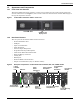
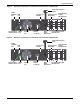
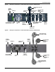
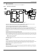
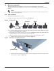
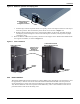

Table Of Contents
- Important Safety Precautions
- Save These Instructions
- Glossary of Symbols
- 1.0 Product Description
- 1.1 Features
- 1.2 Available Models
- 1.3 Appearance and Components
- 1.3.1 Front Panel and Controls
- 1.3.2 Rear Panel Features
- Figure 2 Rear panel components—Liebert GXT4 120V rack/tower, 500, 700, 1000VA model
- Figure 3 Rear panel components—Liebert GXT4 120V rack/tower, 1500VA model
- Figure 4 Rear panel components—Liebert GXT4 120V rack/tower, 2000VA model
- Figure 5 Rear panel components—Liebert GXT4 120V rack/tower, 3000VA model
- Figure 6 Rear panel components—Liebert GXT4 208V rack/tower, 3000VA model
- 1.4 Major Components
- 1.5 Operating Mode
- 2.0 Installation
- 3.0 Operation and Display Panel
- Figure 14 Operation and display panel
- 3.1 LED Indicators
- 3.2 Control Buttons
- 3.3 LCD
- 3.4 Menu Structure
- Figure 15 Menu structure
- 3.4.1 Startup Screen
- 3.4.2 Default Screen
- 3.4.3 Main Menu Screen
- 3.4.4 Prompt List
- 3.4.5 Warning List
- 3.4.6 Fault List
- 4.0 Operation
- 5.0 Communication
- 6.0 Maintenance
- 7.0 Troubleshooting
- 8.0 Battery Cabinet
- 9.0 Specifications
- Table 13 Specifications of GXT4-500RT120 - GXT4-700RT120 and GXT4-1000RT120 models
- Table 14 Specifications of GXT4-1500RT120 - GXT4-3000RT120 and GXT4-3000RT208 models
- Table 15 Battery cabinet specifications
- Table 16 Operating temperature parameters
- Table 17 Battery run times
- 9.1 Product Warranty Registration
- 9.2 Technical Support

Installation
Liebert
®
GXT4
™
12
2.4 Mechanical Installation
The Liebert GXT4 may be installed as a tower or in a rack, depending on space and use
considerations. The Liebert GXT4 may be used alone, as a single UPS, or with up to four battery
cabinets.
2.4.1 Tower Installation
To install the Liebert GXT4 as a tower:
1. Take out support bases from the accessories (see Figure 8).
Figure 8 Support bases
2. If optional Liebert external battery cabinets will be connected to the Liebert GXT4, take out the
spacers shipped with the battery cabinet.
3. Connect the spacers and the support bases as shown in Figure 8. Each Liebert GXT4 needs two
assembled support bases, one in the front and one in the rear.
4. Adjust the direction of the operation and display panel and logo on the Liebert GXT4.
a. Remove the front plastic bezel cover as shown in Figure 9.
Figure 9 Remove the front plastic bezel cover
b. Pull the operation and display panel gently, rotate it 90 degrees clockwise and snap it back
into position, as shown in Figure 10.
NOTE
When installing the UPS or making input and output connections, comply with all relevant
safety codes and standards
Support Bases
Spacers
Connectors
Front Bezel Cover