
Owners manual
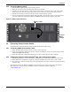
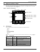
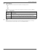
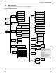
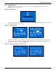
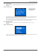

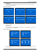
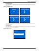
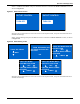
Table Of Contents
- Important Safety Precautions
- Save These Instructions
- Glossary of Symbols
- 1.0 Product Description
- 1.1 Features
- 1.2 Available Models
- 1.3 Appearance and Components
- 1.3.1 Front Panel and Controls
- 1.3.2 Rear Panel Features
- Figure 2 Rear panel components—Liebert GXT4 120V rack/tower, 500, 700, 1000VA model
- Figure 3 Rear panel components—Liebert GXT4 120V rack/tower, 1500VA model
- Figure 4 Rear panel components—Liebert GXT4 120V rack/tower, 2000VA model
- Figure 5 Rear panel components—Liebert GXT4 120V rack/tower, 3000VA model
- Figure 6 Rear panel components—Liebert GXT4 208V rack/tower, 3000VA model
- 1.4 Major Components
- 1.5 Operating Mode
- 2.0 Installation
- 3.0 Operation and Display Panel
- Figure 14 Operation and display panel
- 3.1 LED Indicators
- 3.2 Control Buttons
- 3.3 LCD
- 3.4 Menu Structure
- Figure 15 Menu structure
- 3.4.1 Startup Screen
- 3.4.2 Default Screen
- 3.4.3 Main Menu Screen
- 3.4.4 Prompt List
- 3.4.5 Warning List
- 3.4.6 Fault List
- 4.0 Operation
- 5.0 Communication
- 6.0 Maintenance
- 7.0 Troubleshooting
- 8.0 Battery Cabinet
- 9.0 Specifications
- Table 13 Specifications of GXT4-500RT120 - GXT4-700RT120 and GXT4-1000RT120 models
- Table 14 Specifications of GXT4-1500RT120 - GXT4-3000RT120 and GXT4-3000RT208 models
- Table 15 Battery cabinet specifications
- Table 16 Operating temperature parameters
- Table 17 Battery run times
- 9.1 Product Warranty Registration
- 9.2 Technical Support

Operation and Display Panel
Liebert
®
GXT4
™
16
3.0 OPERATION AND DISPLAY PANEL
This chapter describes the Liebert GXT4 controls, particularly the operation and display panel on the
front of the Liebert GXT4. The panel has four control buttons, seven LED indicators and a liquid
crystal display (LCD), as shown in Figure 14.
Figure 14 Operation and display panel
3.1 LED Indicators
The seven LED indicators on the front of the operation and display panel are:
• Inverter
•Battery
•Bypass
• Programmable Outlet1
• Programmable Outlet2
• ECO Mode
•Fault
Figure 14 shows the indicators’ locations; their descriptions and functions are shown in Table 3.
Table 3 LED indicators
LED Indicators
LED Color
Description
Inverter Green On when the inverter is supplying power
Bypass Amber
On when the load is supplied by the mains through
automatic/manual bypass
Battery Amber On when the load is supplied by the battery
Fault Red On when an error has occurred within the UPS
Programmable Outlet1 Green On when programmable Outlet1 is On
Programmable Outlet2 Green On when programmable Outlet2 is On
ECO Mode Green On when the UPS is in ECO Mode
ESC
Button
UP Button
Programmable Outlet 1 Indicator
Bypass Indicator
DOWN Button
ECO Mode Indicator
LCD
Panel
Programmable Outlet 2 Indicator
Battery Indicator
Fault
Indicator
Inverter Indicator
ENTER Button