
User manual

Single Module UPS Installation
6
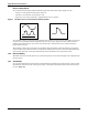
1.4.4 Clearances
The Liebert NX has no ventilation grilles at either side of the UPS. To enable routine tightening of
power terminations within the UPS, in addition to meeting any local regulations, Liebert recom-
mends providing adequate clearance in the front of the equipment for unimpeded passage of person-
nel with the doors fully opened. It is important to leave of 150mm (5.9") clearance behind the UPS to
permit adequate circulation of air coming out of the unit.
1.4.5 Access
The component layout of the UPS supports front and top access while servicing, diagnosing and
repairing the UPS, thus reducing the space requirement for side and rear access.
1.4.6 Final Positioning
The UPS cabinets are fitted with casters on the base to allow ease of movement and positioning.
When the equipment has been finally positioned, ensure the adjustable feet are set so that the UPS
will remain stationary and stable.
1.4.7 Floor Anchoring
Diagrams in 4.0 - Installation Drawings show the location of the holes in the base plate through
which the equipment may be bolted to the floor. If the equipment is to be installed on a raised floor it
should be mounted on a pedestal suitably designed to accept the equipment point loading. Refer to the
base view Figure 21 to design this pedestal.
1.4.8 Cable Entry
Cables can enter the Liebert NX UPS and battery cabinet from below. Cable entry is made possible by
removing a blanking piece fitted at the bottom of equipment to reveal the cable entry hole.
1.5 External Protective Devices
Circuit breakers or other protective devices must be installed in the AC supply, external to the UPS.
This chapter provides guidelines for qualified installers who must have knowledge of local wiring
practices pertaining to the equipment to be installed.
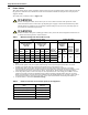
1.5.1 Rectifier and Bypass Input
Overcurrent protection must be installed at the distribution panel of the incoming main supply. The
protection must discriminate with the power cables current capacity and with the overload capacity of
the system (see Table 35). As a guideline, a thermomagnetic circuit breaker, with an IEC 60947-2
trip curve C (normal) for 125% of the current listed in Table 1 is suitable.
Split-Bypass—If a split-bypass is used, install separate protective devices for the rectifier and for
the bypass in the incoming mains distribution panel.
!
WARNING
Casters are strong enough for movement across even surfaces only. Caster failure could occur
if they are subjected to shock loading.
NOTE
Rectifier and bypass input sources must be referenced to the same neutral potential.
NOTE
For IT power systems, four-pole protective devices must be used, external to the UPS, both
upstream of the input distribution panel and downstream (toward the load).