POWER PROTECTION SmartSwitch™ Automatic Transfer Switch Installation and Operation Manual
TABLE OF CONTENTS IMPORTANT SAFETY INSTRUCTIONS . . . . . . . . . . . . . . . . . . . . . . . . . . . . . . . . . . . . . . . . . . . . .1 1.0 INTRODUCTION . . . . . . . . . . . . . . . . . . . . . . . . . . . . . . . . . . . . . . . . . . . . . . . . . . . . . . . 2 1.1 Specifications . . . . . . . . . . . . . . . . . . . . . . . . . . . . . . . . . . . . . . . . . . . . . . . . . . . . . . . . . . . . 2 1.1.1 1.1.2 1.1.3 General Specifications . . . . . . . . . . . . . . . . . . . . . . . . . . . . .
FIGURES Figure 1 Figure 2 Figure 3 Figure 4 Figure 5 Figure 6 Typical SmartSwitch One-Line Diagram . . . . . . . . . . . . . . . . . . . . . . . . . . . . . . . . . . . . . . . . . . 2 Typical 15 to 20 Amp SmartSwitch Rackmount Unit . . . . . . . . . . . . . . . . . . . . . . . . . . . . . . . . 7 Typical 25 to 60 Amp SmartSwitch Underfloor / Wallmount Unit . . . . . . . . . . . . . . . . . . . . . . 8 Typical Input and Output Power Connections . . . . . . . . . . . . . . . . . . . . . . . . . . . . . . .
IMPORTANT SAFETY INSTRUCTIONS ! WARNING THERE ARE NO USER-SERVICEABLE PARTS INSIDE THE REMOVABLE ELECTRONICS MODULE. OPENING OR REMOVING THE COVER OF THE REMOVABLE ELECTRONICS MODULE MAY EXPOSE HAZARDOUS VOLTAGES, EVEN WHEN THE SMARTSWITCH™ IS IN BYPASS. DO NOT ATTEMPT TO SERVICE THIS PRODUCT YOURSELF. REFER ALL SERVICING TO QUALIFIED SERVICE PERSONNEL. NOTE Read the entire User’s Manual before installing and operating the SmartSwitch.
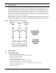
1.0 INTRODUCTION The SmartSwitch™ is an automatic transfer switch designed to provide fast automatic transfers between two independent, synchronous AC power sources to provide continuity of AC power to critical equipment, such as information technology equipment, despite irregularities in either of the two AC input power sources. The transfer is accomplished with sense and transfer times of less than 6 milliseconds.
1.1.
Table 1 SmartSwitch™ Ratings No.
2.0 UNPACKING AND INSTALLATION A quality installation begins on the receiving dock. Upon receipt and before unpacking, inspect the shipping container for damage or mishandling. If carton is damaged, note on shipper’s receipt and check for concealed damage.
2.2 Input and Output Power Connections All wiring should be installed by a qualified electrician. All wiring must comply with NEC and applicable local codes. ! ! WARNING RISK OF ELECTRICAL SHOCK. HAZARDOUS VOLTAGES ARE PRESENT INSIDE THE SMARTSWITCH. VERIFY THAT THE ALL INPUT POWER SOURCES ARE DE-ENERGIZED AND LOCKED OUT BEFORE MAKING CONNECTIONS INSIDE THE UNIT. THE SMARTSWITCH IS INTENDED TO BE FED FROM TWO SOURCES.
Figure 2 Typical 15 to 20 Amp SmartSwitch Rackmount Unit 17.25" (438) 18.5" (469) 0.85" (21.5) 3.5" (88.9) 0.279"x0.406" (7x10) 5.
Figure 3 Typical 25 to 60 Amp SmartSwitch Underfloor / Wallmount Unit If the unit is furnished with input power cables, the input power connections are made to the receptacles matching the input power plugs furnished located in close proximity to the SmartSwitch (typically within 3 feet). The input power connections to the SmartSwitch must include overcurrent protection included as part of the supply power distribution system.
NOTE The two input sources need to be nominally of the same voltage level, frequency and phase rotation. To ensure virtually uninterrupted transfers between the two AC sources, the two input sources must be synchronized, typically within 5 to 15 electrical degrees. For single phase circuits, be sure to use the same phase from each input power source to maintain synchronized inputs to the SmartSwitch. Figure 4 shows the typical input and output power connections to the SmartSwitch.
2.3 Grounding Proper, NEC-specified equipment grounding is required for safety purposes. An insulated equipment grounding conductor is recommended to be run with each input and output power connection. The equipment grounding conductors should be at least the minimum size conductor per NEC Table 250-95 based on the supply overcurrent protection device. If conduit or other wireway is used as the grounding means, adequate electrical continuity must be maintained at all conduit connections.
3.0 OPERATING INSTRUCTIONS NOTE Read the entire operating instructions section before placing the SmartSwitch into operation. NOTE For continued protection against a source failure, periodic testing of the SmartSwitch is recommended. For manual testing, see the transfer control instructions. 3.
3.3 RS-232 Communications Port The SmartSwitch contains an RS-232 ASCII communications port for changing user settings and remote monitoring of unit status and alarm information. The RS-232 port connections are to a 9-pin “D” connector located on the outside of the unit. See Figure 2 and Figure 3 for the location of the port and Figure 5 for the port connections.
Table 5 Example View Event Log Response DATE TIME DESCRIPTION 10/21/97 16:34:39 Transferred to Preferred 10/21/97 16:34:39 Transfer Test Passed 10/21/97 16:34:39 Transferred to Alternate 10/21/97 16:34:38 Transfer Test Initiated 10/21/97 16:34:38 Alternate Source Available 09/27/97 07:22:11 In Sync 09/27/97 07:21:08 Out of Sync 06/01/97 02:10:32 Transferred to Preferred 06/01/97 02:10:29 Preferred Source Available 06/01/97 01:29:13 Transferred to Alternate 06/01/97 01:29:
4.0 OPERATOR CONTROLS 4.1 Bypass/Transfer Control Switch The SmartSwitch is furnished with a Bypass/Transfer Control switch. The switch is located behind the hinged, keylocked cover. Figure 6 shows the switch positions. Normal Mode. The switch should be left in the “Normal” position for automatic transfer control. Automatic transfer control is inhibited in all switch positions other than the “Normal” position.
5.0 OPERATING GUIDELINES After installation, the following operating guidelines can be used for standard equipment operation. These guidelines should be reviewed for any special equipment modifications, special site conditions, or company policies that may require changes to these operating guidelines. Initial System Turn-On. After the initial installation, equipment relocation, or extended period of inoperation, perform the initial system checkout.
Transfer Control switch to “Bypass To S2” position. If source 2 is not available and the load is not connected to source 2 before the switch is rotated to the “Bypass To S2” position, power to the load may be interrupted. If the load is connected to source 1 and the SmartSwitch will not transfer the load to source 2, initiate a bypass to source 1. System Shutdown. Power to both SmartSwitch inputs must be turned OFF to ensure system shutdown. Transfer Test.
6.0 MAINTENANCE ! ! WARNING THERE ARE NO USER-SERVICEABLE PARTS INSIDE THE REMOVABLE ELECTRONICS MODULE. OPENING OR REMOVING THE COVER OF THE REMOVABLE ELECTRONICS MODULE MAY EXPOSE HAZARDOUS VOLTAGES, EVEN WHEN THE SMARTSWITCH IS IN BYPASS. DO NOT ATTEMPT TO SERVICE THIS PRODUCT YOURSELF. REFER ALL SERVICING TO QUALIFIED SERVICE PERSONNEL. CAUTION The unit is supplied by two power sources.
18 Maintenance
SmartSwitch™ Automatic Transfer Switch Technical Support U.S.A. Outside the U.S.A. 1-800-LIEBERT +614-841-6755 or 1-800-222-5877 U.K. +44 (0) 1628 403200 France +33 (0) 1 43 60 01 77 Germany Italy Netherlands Web site Worldwide FAX tech support +49 89 99 19 220 +39 2 98250 1 +31 (0) 475 503333 http://www.liebert.com +614-222-5877 option #4 The Company Behind The Products With more than 500,000 installations around the globe, Liebert is the world leader in computer protection systems.