MONITORING UNIVERSAL MONITOR USER MANUAL
TABLE OF CONTENTS 1.0 INTRODUCTION 1.1 1.2 1.3 1.4 1.5 1.6 1.7 1.8 1.9 1.10 1.11 Methods of Viewing and Configuring the Universal Monitor . . . . . . . . . . . . . . . . . . . . . . . . . Data Logs . . . . . . . . . . . . . . . . . . . . . . . . . . . . . . . . . . . . . . . . . . . . . . . . . . . . . . . . . . . . . . . . . . Optional Features. . . . . . . . . . . . . . . . . . . . . . . . . . . . . . . . . . . . . . . . . . . . . . . . . . . . . . . . . . . . Available Alarms . . . . . . . . . . . . .
5.0 WIRING AND CONNECTIONS - OPTIONAL EXPANSION BOARD 5.1 5.2 Wiring Specifications . . . . . . . . . . . . . . . . . . . . . . . . . . . . . . . . . . . . . . . . . . . . . . . . . . . . . . . . 25 Connecting Inputs and Outputs . . . . . . . . . . . . . . . . . . . . . . . . . . . . . . . . . . . . . . . . . . . . . . . 26 5.2.1 5.2.2 5.2.3 5.3 Connecting Digital Inputs . . . . . . . . . . . . . . . . . . . . . . . . . . . . . . . . . . . . . . . . . . . . . . . . . . . . .
9.5 Setup System - Setup Sensor. . . . . . . . . . . . . . . . . . . . . . . . . . . . . . . . . . . . . . . . . . . . . . . . . . 49 9.5.1 9.5.2 9.5.3 9.5.4 9.5.5 9.5.6 9.5.7 9.5.8 9.5.9 9.5.10 9.5.11 9.6 58 58 59 59 Modem Setup - Initialization String . . . . . . . . . . . . . . . . . . . . . . . . . . . . . . . . . . . . . . . . . . . . . Modem Setup - Additional Features (Service Terminal Interface only) . . . . . . . . . . . . . . . . . Pager Setup - Pager Number and PIN . . . . . . . . . . . . . .
APPENDIX A - SERVICE TERMINAL INTERFACE . . . . . . . . . . . . . . . . . . . . . . . . . . . . . . . . . . . . . . . 85 A.1 Comparison of Functions: LCD and Service Terminal Interface. . . . . . . . . . . . . . . . . . . . . . 85 A.2 Connecting to the Service Terminal Interface . . . . . . . . . . . . . . . . . . . . . . . . . . . . . . . . . . . . 86 A.2.1 A.2.2 A.2.3 A.2.4 A.2.5 A.3 View Active Alarms . . . . . . . . . . . . . . . . . . . . . . . . . . . . . . . . . . . . . . . . . . . . . . . . . .
FIGURES Figure 1 Figure 2 Figure 3 Figure 4 Figure 5 Figure 6 Figure 7 Figure 8 Figure 9 Figure 10 Figure 11 Figure 12 Figure 13 Figure 14 Figure 15 Small enclosure—external features . . . . . . . . . . . . . . . . . . . . . . . . . . . . . . . . . . . . . . . . . . . . . . . . . . 2 Large enclosure—internal features . . . . . . . . . . . . . . . . . . . . . . . . . . . . . . . . . . . . . . . . . . . . . . . . . . 2 Typical Configuration . . . . . . . . . . . . . . . . . . . . . . . . . . . . . . . . . .
Table 32 Table 33 Table 34 Table 35 Table 36 Table 37 Table 38 Table 39 Table 40 Service phone number dialing results . . . . . . . . . . . . . . . . . . . . . . . . . . . . . . . . . . . . . . . . . . . . . . . 74 Guidelines for dialing service phone number . . . . . . . . . . . . . . . . . . . . . . . . . . . . . . . . . . . . . . . . . 74 Automatic / manual control - output points. . . . . . . . . . . . . . . . . . . . . . . . . . . . . . . . . . . . . . . . . . .
Introduction 1.0 INTRODUCTION The Liebert Universal Monitor’s extensive capabilities can put it at the heart of your protective network. The Universal Monitor employs local alarming and remote paging services to keep personnel on-site and at remote locations apprised of the status of equipment. The panel can interface with any device that closes an electrical contact or has a 4-20 mA signal.
Introduction 1.5 Outside Enclosure Overview The enclosure for the Universal Monitor’s controller board comes in two sizes: • The large enclosure is designed to accommodate the Transformer Module and future components, in addition to the controller board. • The small enclosure is built to hold the controller board only. Both enclosures are 2-3/4" deep. Both enclosures have a built-in liquid crystal display (LCD) and a key lock, as shown in the example below.
Introduction 1.6 Typical Configuration Figure 3 shows an example of external devices connected to the Universal Monitor’s controller board. There may be up to eight digital output, eight digital input and four analog input devices connected. The optional Universal Monitor Expansion Board provides additional connections for eight output and sixteen digital input devices.
Introduction 1.7 Controller Board Overview The Universal Monitor’s controller board has connectors for eight digital inputs, four analog inputs and eight digital outputs, as shown below. The board comes complete with light emitting diodes (LEDs) to display the status of monitored devices, a battery pack for short-term backup, communications ports, power connections and other features necessary to monitor and protect your operation.
Introduction Table 1 Controller board components (continued) Item K - Digital output lossof-power jumper Description One of eight output jumpers. Each digital output has a jumper to set the fail-safe position of the output point when power fails. The OFF position makes the contact Normally Open (factory default). The ON position makes the contact Normally Closed. Note: The jumper position has no effect on the contact when the Universal Monitor has power.
Introduction 1.8 Optional Expansion Board Overview The Universal Monitor Expansion Board, purchased separately, has connectors for 16 digital inputs and eight digital outputs, as shown below. The board has light emitting diodes (LEDs) to display the status of monitored output devices, communications ports for connection to the Universal Monitor, power connections and other features necessary to monitor and protect your operation. J - 24VAC power connector USE COPPER (CU) CONDUCTORS ONLY.
Introduction 1.9 LED Indicators The Universal Monitor’s controller board has LED indicators that show the status of inputs, outputs and the common alarm, as well as the modem and SiteScan Web connections.
Introduction 1.10 LED Indicators - Optional Expansion Board The optional Expansion Board, purchased separately, has LED indicators that show the status of inputs and outputs. USE COPPER (CU) CONDUCTORS ONLY.
Introduction 1.11 Typical Sequence Figure 4 shows a typical sequence of how the Universal Monitor functions after detecting a change in a monitored unit or area. Many responses depend on configuration settings. This example shows what happens when an analog sensor input reaches a high setpoint—assuming the input is defined as alarmable and is set up to trigger a response in an output—and when the condition returns to normal.
Installation - Main Board 2.0 INSTALLATION - MAIN BOARD This section provides instructions for installing, mounting and connecting power to the Universal Monitor. For information on the optional Expansion Board, see 3.0 - Installation - Optional Expansion Board. 2.
Installation - Main Board 2.2 Surface-Mounting the Universal Monitor NOTE Removing the conduit knockouts before mounting the Universal Monitor on the wall will ease installation and prevent strain on the mounting hardware and wall. It is imperative to remove the knockouts if the unit is to be flush-mounted. After determining where to place the unit, check to ensure that you have all the hardware required to install the panel on the surface of a wall. Obtain the needed tools and material.
Installation - Main Board 2.3 Flush-Mounting the Universal Monitor NOTE Removing the conduit knockouts before mounting the Universal Monitor on the wall will ease installation and prevent strain on the mounting hardware and wall. It is imperative to remove the knockouts if the unit is to be flush-mounted. The rectangular access doors on the top and bottom of the Universal Monitor must be reversed so they slide the opposite direction.
Installation - Main Board 2.4 Connect Power to the Universal Monitor The Universal Monitor requires 24VAC for proper operation. Liebert recommends using the optional Transformer Module manufactured by Liebert or another UL-approved Class 2 power unit to obtain proper voltage. If the power unit is not a Class 2 circuit, it must be protected with an IEC 5 x 20mm time lag 2A fuse. For information, consult your local dealer, Liebert representative or the Liebert Worldwide Support Group.
Installation - Main Board 2.4.2 Termination and Mounting - Large Enclosure ! ! CAUTION The 115VAC/230VAC Transformer Module must be connected to a branch circuit with 15A branch circuit protection. This equipment is intended to be installed by a qualified and certified electrician who must review and approve customer supplied wiring and circuit breakers, verify correct input and grounded connections to ensure compliance with the technical standards and national and local electrical codes.
Installation - Main Board Troubleshooting - Transformer Module A common problem and possible solution are shown in the table below. For further information or if you have other problems with the unit, consult your local dealer, Liebert representative or the Liebert Worldwide Support Group. Problem 24VAC power not available from TB1 or TB2 2.4.3 Possible Solution Replacement Fuse Part Numbers • LITTLEFUSE 218002 or • BUSSMANN GDC-2A Check fuse for respective output (TB1 or TB2).
Installation - Optional Expansion Board 3.0 INSTALLATION - OPTIONAL EXPANSION BOARD This section provides instructions for installing, mounting and connecting power to the optional Expansion Board. The Expansion Board enclosure is identical to the Universal Monitor’s small enclosure. 3.
Installation - Optional Expansion Board 3.2 Surface-Mounting the Optional Expansion Board NOTE Removing the conduit knockouts before mounting the optional Expansion Board on the wall will ease installation and prevent strain on the mounting hardware and wall. It is imperative to remove the knockouts if the unit is to be flush-mounted. After determining where to place the optional Expansion Board, check to ensure that you have all the hardware required to install the panel on the surface of a wall.
Installation - Optional Expansion Board 3.3 Flush-Mounting the Optional Expansion Board NOTE Removing the conduit knockouts before mounting the optional Expansion Board on the wall will ease installation and prevent strain on the mounting hardware and wall. It is imperative to remove the knockouts if the unit is to be flush-mounted. The rectangular access doors on the top and bottom of the Expansion Board must be reversed so they slide the opposite direction.
Installation - Optional Expansion Board 3.4 Input Power Connections - Optional Expansion Board The optional Expansion Board requires 24VAC for proper operation. Liebert recommends using the optional Transformer Module manufactured by Liebert or another UL-approved Class 2 power unit to obtain proper voltage. If the power unit is not a Class 2 circuit, it must be protected with an IEC 5 x 20mm time lag 2A fuse.
Wiring and Connections - Main Board 4.0 WIRING AND CONNECTIONS - MAIN BOARD CAUTION ! 4.1 Switch OFF electric power to the Universal Monitor before installing any wiring to the unit or changing input or output connections. The Power On/Off switch is in the top left corner of the unit, just below the battery pack.
Wiring and Connections - Main Board 4.2 Connecting Digital Inputs and Digital Outputs The digital inputs and digital outputs are found on the lower right side of the Universal Monitor’s printed wiring assembly board. There are two terminal blocks for the inputs—one green, the other black. There are two terminal blocks for the outputs—one green, the other black. To determine the proper wire size, see Table 7 - Wiring specifications - main board.
Wiring and Connections - Main Board 4.2.3 Setting the Digital Output Jumpers Each digital output has an associated jumper to define its operation when power is interrupted and there is no battery backup to the board. This puts the Universal Monitor in a fail-safe mode and ensures proper functioning when the board has no power or battery backup. The Universal Monitor comes from the factory with all digital output jumpers in the OFF position (normally open).
Wiring and Connections - Main Board 4.3.1 Setting the 12VDC/24VDC Analog Power Jumper The analog power jumper sets the common voltage that is applied to all of the analog input connections. The jumper permits the user to modify the voltage supplied to the sensors, according to the power requirements. The factory default position is 24VDC; it may be changed to 12VDC. Analog power jumper To change the analog power jumper setting: 1. Find the black analog jumper on the circuit board, as shown at right.
Wiring and Connections - Main Board 4.4 Connecting Common Alarm Outputs The common alarm relay, found in the top right corner of the Universal Monitor, permits the user to connect auxiliary notification equipment, such as lights, horns and sirens, to the Universal Monitor. To determine the proper wire size, see Table 7 - Wiring specifications - main board. There are two connectors for the common alarm output. However, the connectors are not individual relay outputs.
Wiring and Connections - Optional Expansion Board 5.0 WIRING AND CONNECTIONS - OPTIONAL EXPANSION BOARD 5.1 ! CAUTION ! WARNING Remove all power before installing any wiring to the Expansion Board or changing input or output connections. “RISK OF ELECTRIC SHOCK” - More than one disconnect switch may be required to de-energize the equipment before servicing.
Wiring and Connections - Optional Expansion Board 5.2 Connecting Inputs and Outputs The Universal Monitor’s optional Expansion Board permits the addition of 16 input and eight output devices. This section describes how to connect devices to the Expansion Board’s inputs and outputs. To determine the proper wire size, see Table 9. NOTE Each terminal block is a removable assembly to permit easier connection of more than one input at a time.
Wiring and Connections - Optional Expansion Board 5.2.2 Connecting Digital Outputs The eight digital outputs are found at the top of the Expansion Board, as shown below. These inputs are numbered 9 through 16. (Note that the digital outputs on the main board of the Universal Monitor are numbered 1 - 8.) OUTPUT TERMINAL BLOCKS - Note numbering keys above terminal blocks; outputs are numbered from left (9) to right (16) USE COPPER (CU) CONDUCTORS ONLY.
Wiring and Connections - Optional Expansion Board 5.2.3 Setting the Digital Output DIP Switches Each digital output on the optional Expansion Board has an associated DIP switch that can determine its operation in the event of loss of communication with the Universal Monitor or loss of power. When the Universal Monitor calls for an Expansion Board output to be ON, it sends a command to the Expansion Board to turn the output to the ON state; this is signified by the output LED being ON.
Wiring and Connections - Optional Expansion Board 5.3 Connect to the Universal Monitor Two steps are required to establish connection between the optional Expansion Board and the Universal Monitor. 5.3.1 Connect EIA485 Connectors to Main Board To connect the optional Expansion Board to the Universal Monitor: 1. Turn OFF electrical power to the Universal Monitor and disconnect power from the Expansion Board. 2. If necessary, remove a conduit knockout to permit wire entry into each enclosure. 3.
Overview of Menus 6.0 OVERVIEW OF MENUS There are two ways to access the Universal Monitor: the LCD on the front of the enclosure and the Service Terminal Interface, which is accessible through any computer using a communications program. Many viewing and configuration tasks can be performed through either interface, but some are available only through the Service Terminal Interface. • Step-by-step instructions for all functions appear in Sections 7.0 through 9.0.
Overview of Menus 6.1 Opening Screen Overview The Universal Monitor displays the Opening Screen at startup, as shown in Figure 12. • If any alarms are active, the Current Alarm screen appears. (Pressing any key on the LCD keypad will silence the audible alarm.) • If any analog input sensors are connected, the LCD screen will alternately display the Opening Screen and a screen showing the analog value of each sensor. If no alarms are present, the Main Menu appears. 6.
View Status Options 7.0 VIEW STATUS OPTIONS NOTE For ease of understanding, this section uses the LCD interface to illustrate most instructions, except for features that are available only through the Service Terminal Interface. All Service Terminal Interface screens appear in Appendix A - Service Terminal Interface.
View Status Options 7.1 View Active Alarms Main Menu The Active Alarm screen displays all alarms that are occurring, up to a > VIEW STATUS SYSTEM AND CONTROL maximum of 33. ↑ ↓=NEXT ↵ =SELECT A Current Alarm screen appears automatically whenever an alarm occurs—except during setup. This screen can display only the two most recent active alarms. To view any other active alarms, use the View View Status Menu Active Alarms feature.
View Status Options 7.2 View Alarm Log Main Menu The Alarm Log contains up to 99 records of alarms that have occurred. > VIEW STATUS SYSTEM AND CONTROL Records are added to this log as alarms occur. To view the Alarm Log: ↑ ↓=NEXT • From the Main Menu, use the arrows ↑ ↓ to choose View Status, then press Enter ↵ . • From the View Status Menu, use the arrows ↑ ↓ to choose View Alarm Log, then press Enter ↵ . 7.2.
View Status Options 7.3 View Event Log Main Menu > VIEW STATUS In addition to alarms, the Universal Monitor tracks other changes in SYSTEM AND CONTROL the Event Log to assist users with verifying operational and troubleshooting problems. Events reflect changes in the status of an input that ↑ ↓=NEXT ↵ =SELECT is defined as an event or the change of state of an output (i.e., manually forced ON or OFF).
View Status Options 7.4 View Trend Log Main Menu The Universal Monitor takes readings of configured analog input sen- > VIEW STATUS SYSTEM AND CONTROL sors at regular intervals and stores them in four separate trend logs, one for each sensor. The time interval is 30 minutes. Each log contains ↑ ↓=NEXT ↵ =SELECT up to 100 records. Follow these steps to select a sensor and view its trend log: 7.4.
View Status Options 7.5 View Input Status Main Menu The Input Status option allows you to view the current status of all > VIEW STATUS SYSTEM AND CONTROL inputs: the four analog sensor inputs and the eight digital inputs. If the optional Expansion Board is used, the additional 16 digital inputs can ↑ ↓=NEXT ↵ =SELECT also be viewed. To view the Input Status: View Status Menu • From the Main Menu, use the arrows ↑ ↓ to choose View Status, then press Enter ↵ .
View Status Options 7.6 View Output Status Main Menu The Output Status option allows you to view the current status of all eight outputs. If the optional Expansion Board is used, the additional eight digital outputs can also be viewed. To view the Output Status: • From the Main Menu, use the arrows ↑ ↓ to choose View Status, then press Enter ↵ . • From the View Status Menu, use the arrows ↑ ↓ to choose View Output Status, then press Enter ↵ . 7.6.
View Status Options 7.7 View Pager Numbers Main Menu > VIEW STATUS The Universal Monitor may be set up to dial pager numbers when an SYSTEM AND CONTROL alarm is detected. Up to four pagers may be configured, as described in 9.8 - Setup System - Setup Modem & Pagers. ↑ ↓=NEXT ↵ =SELECT The View Pager Numbers option allows you to view the pager numbers and PINs for all configured pagers. Use the following steps to select a View Status Menu pager and view its information. 7.7.
Silence Alarm & Backup Log Files (Service Terminal Interface) 8.0 SILENCE ALARM & BACKUP LOG FILES (SERVICE TERMINAL INTERFACE) This section describes two features that are available in the Service Terminal Interface: • Silence Alarm • Backup Log Files 8.1 Silence Alarm (Service Terminal Interface) The Silence Alarm menu item allows you to silence the audible alarm and reset the Common Alarm Relay output if the common alarm is configured to reset with silence.
Silence Alarm & Backup Log Files (Service Terminal Interface) 8.2 Back Up Log Files (Service Terminal Interface only) The Universal Monitor maintains three types of logs—alarm, event and trend—that may be backed up to a remote computer. This feature is available only through the Service Terminal Interface. To back up any of the alarm, event or trend logs: 1. Connect to the Universal Monitor either from a remote computer or through the RS232 port (see A.2 - Connecting to the Service Terminal Interface). 2.
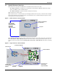
Silence Alarm & Backup Log Files (Service Terminal Interface) NOTE The following instructions refer to the Microsoft® Windows® HyperTerminal program. These steps may vary for other communications programs. 5. At the top of the HyperTerminal window, shown below, click on Transfer, then on Receive File. Enter folder Select Xmodem Enter filename for example, alarm.log 6.
System and Control Options 9.0 SYSTEM AND CONTROL OPTIONS NOTE For ease of understanding, this section uses the LCD interface to illustrate most instructions, except for features that are available only through the Service Terminal Interface. All Service Terminal Interface screens appear in Appendix A - Service Terminal Interface.
System and Control Options Figure 14 shows the main options available from the System & Control menu. Figure 14 Menu overview - System and Control menu Opening Screen UNIVERSAL MONITOR DD-MON-YY HR:MM:SS VX.XXX.
System and Control Options 9.2 Setup System - Overview The Setup System screen displays seven options that allow you to configure input and output devices and their relationships, the common alarm, the modem, pagers to be dialed when alarms occur, and a variety of system details, such as login password and system date and time: • • • • • • • • 9.
System and Control Options 9.3.1 Change Label (Name of Input) Setup Input Menu Each input has a default label (Input_01, Input_02, etc.) that you may change to a more descriptive name for ease in recognizing alarms and events associated with the input. The label may consist of up to eight characters (see Table 20 for valid characters). • From the Setup Input Menu, choose Label for the selected input—Label: Input_01 in the example at right—and press Enter ↵ .
System and Control Options 9.3.4 Set Up Alarmable Inputs in Latched or Unlatched Mode Setup Input Menu Alarmable input points may be set up in Latched mode (Y), which requires the user to clear the Universal Monitor alarms after an alarm has occurred, or Unlatched mode (N), in which alarms will automatically clear after a return-to-normal state. The default setting for alarmable inputs is N (Unlatched). Any input defined as an event is automatically Unlatched.
System and Control Options 9.4 Setup System - Setup Common Alarm The audible alarm sounds after the Universal Monitor detects an alarm condition in any input that has been defined as alarmable, including digital and analog sensor inputs. Once the alarm is silenced, there are two options: • By default, the common alarm remains energized until the input alarm is cleared. • You may change this setting to de-energize the common alarm automatically once the alarm is silenced.
System and Control Options 9.5 Setup System - Setup Sensor The Universal Monitor has four analog sensor input points that may be configured individually. The panel monitors connected equipment for any 4-20 mA input—for example, temperature and humidity. To configure a sensor: Setup System Menu Log In and Choose Setup System • From the Main Menu, use the arrows ↑ ↓ to choose System and Control, then press Enter ↵ (see 9.1 - Login for help). • Enter your password at the Login screen.
System and Control Options 9.5.1 Identify the Sensor as Connected Setup Sensor Menu To make use of an analog sensor, you must specify it as Connected (Y). By default, analog sensors are Not connected (N). • From the Setup Sensor Menu, choose Connected, as shown at right, and press Enter ↵ . • To change this feature, use the arrows ↑ ↓ to choose Y (Yes - Connected) or N (No - Not connected), then press Enter ↵ . SETUP SENSOR_1 > CONNECTED : N LABEL: SENSOR_1 ↑ ↓=NEXT ↵ =SELECT UNITS: ___ 4 mA: -999.
System and Control Options 9.5.4 Change 4 mA Value Setup Sensor Menu For the 4 mA value, enter the smallest value for the range of the sensor—for example, 50°F for a temperature sensor with a range of 50°F to 90°F. The default value for each sensor is -999.9. Values that can be entered range from -999.9 to +999.9. To enter a new value: • From the Setup Sensor Menu, choose 4 mA for the selected sensor and press Enter ↵ . • To change the 4 mA value: • Use the arrows ↑ ↓ to choose a character.
System and Control Options 9.5.7 Define Sensor as Alarmable or Event Setup Sensor Menu Each sensor may be defined as Alarmable (AL) or as an Event (EV). • For a sensor defined as alarmable, the following alarm reactions occur when the high-setpoint threshold is crossed: the LCD flashes, the audible horn sounds, configured pager numbers will be notified and a record is entered in the Alarm Log. • For a sensor defined as an event, the high-setpoint occurrence is recorded in the Event Log.
System and Control Options 9.5.9 Change Low Setpoint Setup Sensor Menu The Low Setpoint value is typically above the 4 mA value for the sensor. For example, if the 4 mA value is 50°F, the Low Setpoint might be 60°F. When the sensor crosses below this value, an alarm or event will occur, depending on the sensor configuration. The default Low Setpoint for each sensor is -950.0.
System and Control Options 9.5.11 Set Up Delay Time Setup Sensor Menu Each sensor may be set up with a specified time delay between the triggering of a high or low setpoint—a monitored sensor crosses the high or low setpoint threshold—and any response by the Universal Monitor. This feature can prevent transient conditions from prompting unnecessary responses.
System and Control Options 9.6 Setup System - Setup I/O Matrix The Setup I/O Matrix menu allows you to configure the Universal Monitor’s digital and analog inputs to trigger various actions in any or all of the 16 outputs—eight on the main board and another eight if the optional Expansion Board is used. Each output can be set up to respond to more than one digital or analog input, including the additional 16 inputs available via the optional Expansion Board. Almost any mapping combination can be used.
System and Control Options Map Input to Expansion Board Output • From the Select Outputs menu, select Map to Exp Board if you Select Outputs want to map the selected input to an output on the optional ExpanSELECT OUTPUTS sion Board. These outputs are identified as Outputs 9-16. MAP TO MAIN BOARD • On the Output Map screen, you may map the selected input to any > MAP TO EXP BOARD ↑ ↓=NEXT ↵ =SELECT of the eight outputs (9-16)—or to more than one output, if desired.
System and Control Options 9.6.2 Set Up Mapping for an Analog Sensor Input • Use the arrows ↑ ↓ to choose Map Sensor To Outpt from the Map Input/Sensor Menu, and press Enter ↵ . • From the Select Sensor Menu, choose the input you want—for example, Sensor_1 High Stpt—and press Enter ↵ . Map Sensor to Main Board Output • From the Select Outputs menu, select Map to Main Board if you want to map the selected sensor to an output on the Universal Monitor main board. These outputs are identified as Outputs 1-8.
System and Control Options 9.7 Setup System - Setup Output Setup System Menu The Universal Monitor has eight outputs that may be configured individually. If the optional Expansion Board is used, its additional eight digital outputs may be renamed. The outputs may have a wide variety of Liebert or other manufacturers’ equipment connected for configured responses to input alarms and events.
System and Control Options 9.7.3 Set Expansion Board Output by DIP Switch If you choose Change State from the Setup Output Menu for an Expansion Board output (OUTPUT09-16), the screen displays a message that the state must be set by DIP switch, as shown at right.
System and Control Options 9.8 Setup System - Setup Modem & Pagers To use the modem and pager features, be sure to connect the phone line connector to a telephone wall jack using an RJ11 cord, as described in 4.6.2 - Phone Line Connector. 9.8.1 Modem Setup - Initialization String The Universal Monitor has an on-board modem that offers dial-up access to all LCD functions as well as features available only through the Service Terminal Interface (see A.
System and Control Options Select Modem Setup Setup System Menu 4. From the Setup System Menu, shown at right, use the arrows ↑ ↓ to SETUP INPUT choose Setup Modem&Pagers and press Enter ↵ . SETUP COMMON ALARM SETUP SENSOR 5. Use the arrows ↑ ↓ to choose Setup Modem from the Pagers & SETUP I/O MATRIX Modem Menu and press Enter ↵ . ↑ ↓=NEXT ↵ =SELECT 6.
System and Control Options 9.8.2 Modem Setup - Additional Features (Service Terminal Interface only) The Service Terminal Interface offers four additional options for the modem that are not available through the LCD interface: • • • • Enter Universal Monitor phone number Enable modem diagnostic messages Change modem dial prefix Change modem hang up delay after a call To access these options: • Connect to the Universal Monitor either from a remote computer or through the RS232 port (see A.
System and Control Options Enable Modem Diagnostic Messages Enabling modem diagnostics will provide the following additional information about the modem to the computer using the Service Terminal Interface: Hang-up modem Modem model number No dial tone No carrier Busy No answer Pager checksum error Pager pin number error Error (indicates incorrect phone number, dial prefix or modem initialization string) For alphanumeric pager failures: Paging company non answer on 1st Paging company non answer on 2nd Pagi
System and Control Options 9.8.3 Pager Setup - Pager Number and PIN The Universal Monitor may be configured to dial numeric or alphanumeric pagers when an alarm is detected. You may enter up to four pager numbers—all configured pagers will be dialed each time an alarm occurs. For each configured pager, you must enter the pager number to be dialed and the pager’s Personal Identification Number (PIN). See 10.1 - Universal Monitor Specifications for supported pager settings.
System and Control Options Enter a Pager Number Setup Pager Menu • From the Setup Pager Menu, choose Setup Pager Number for the selected pager—Setup Pager 1 Number in the example at right—and press Enter ↵ . • See Table 30 for guidelines on entering the pager number, which may consist of up to 40 characters. To enter the pager number: • Use the arrows ↑ ↓ to choose a character. • Press Enter ↵ to advance to the next character position. • When finished, press Enter ↵ again.
System and Control Options 9.8.4 Pager Setup - Communications Check (Service Terminal Interface only) The Service Terminal Interface offers two additional options for pager setup, which are not available through the LCD interface: • Enable communications check • Enter time to perform communications check To access these options: • Connect to the Universal Monitor either from a remote computer or through the RS232 port (see A.2 - Connecting to the Service Terminal Interface).
System and Control Options Enable Communications Check Enabling this function permits a daily communications test between the Universal Monitor and the selected pager. Once each day the Universal Monitor dials the pager at a specified time and sends this message: “UNIVERSAL MONITOR COMM CHECK.” (The time of the test is specified at the next prompt, Enter Time To Perform Communications Check.) • At the Enable Communications Check prompt, enter Y (Yes - enable) or N (No - disable).
System and Control Options 9.
System and Control Options 9.9.1 Change Password Setup System Info Menu A password is required to access the Universal Monitor’s system and control options, as described in 9.1 - Login. The password consists of four characters (see Table 20 for valid characters). The default password is AAAA. Change the Password To change the password: • From the Setup System Info Menu, use the arrows ↑ ↓ to choose Change Password, then press Enter ↵ .
System and Control Options 9.9.3 Setup Site ID Setup System Info Menu You may enter a Site ID to identify the Universal Monitor’s location, using a name that may consist of up to 40 characters (see Table 20 for valid characters). The Site ID will appear with each alarm. To enter or change the Site ID: • From the Setup System Info Menu, use the arrows ↑ ↓ to choose Setup Site ID, then press Enter ↵ . • To enter a Site ID: • Use the arrows ↑ ↓ to choose a character.
System and Control Options 9.9.5 Backup and Upload Configuration File (Service Terminal Interface only) This operation may be performed only through the Service Terminal Interface. It permits the user to make a copy of the Universal Monitor’s configuration settings and save it as a file on the computer connected through the RS232 port. Should the need arise, the user can upload the configuration file from the computer to the Universal Monitor, instead of re-entering the settings manually.
System and Control Options Back Up the Configuration File 8. At the prompt to Initiate a Backup of Configuration File, enter Y (Yes - begin) or N (No - cancel). The current setting appears in brackets—[N] in the following example. >INITIATE A BACKUP OF CONFIGURATION FILE-YES(Y) OR NO(N)? >[N] >[ NOTE The following instructions refer to the Microsoft Windows HyperTerminal program. These steps may vary for other communications programs. 9.
System and Control Options Upload the Configuration File 13. At the prompt to Initiate an Upload of Configuration File, enter Y (Yes - begin) or N (No - cancel). The current setting appears in brackets—[N] in the following example. >INITIATE AN UPLOAD OF CONFIGURATION FILE-YES(Y) OR NO(N)? >[N] >[ NOTE The following instructions refer to the Microsoft Windows HyperTerminal program. These steps may vary for other communications programs. 14.
System and Control Options 9.9.6 Setup Serv Ph Num - Enter Phone Number The Service Phone Number (Serv Ph Num) is used for remote monitoring by Liebert Global Services. The number is designed to allow remote monitoring services to connect to the Universal Monitor. All alarms will be sent to this number. When an alarm occurs, this number is dialed before any of the four pager numbers.
System and Control Options 9.9.7 Setup Serv Ph Num - Communications Check (Service Terminal Interface only) The Service Terminal Interface offers two additional options for setting up the Service Phone Number (Serv Ph Num) that are not available through the LCD interface: • Enable communications check • Enter time to perform communications check To access these options: • Connect to the Universal Monitor either from a remote computer or through the RS232 port (see A.
System and Control Options 9.9.8 Factory Defaults Setup System Info Menu At any time, you may restore all default values for settings in the Universal Monitor as it was shipped. NOTE This action will overwrite any configuration settings. You may want to back up your settings before restoring the factory defaults. See Backup and Upload Configuration File (Service Terminal Interface only) in A.6.7 - Setup System Info for details on backing up settings using the Service Terminal Interface.
System and Control Options NOTE The following instructions refer to the Microsoft Windows HyperTerminal program. These steps may vary for other communications programs. 2. The firmware update is a two-step process—this step describes how to upload the file prog###.s19 (where ### is a number—for example, prog118.s19) to the Universal Monitor: a. At the top of the HyperTerminal window, shown below, click on Transfer, then on Send File. Enter filename prog###.s19 or flash###.
System and Control Options 9.9.10 Initiate Remote Alarm Test (Service Terminal Interface only) The service phone number is used for remote monitoring by Liebert Global Services. The Service Terminal Interface may be used to test communications between the Universal Monitor and the service modem. This test will send a “DIAL OUT TEST PASSED” message to the service phone number.
System and Control Options 9.10 Setup Exp Board - Optional Expansion Board By default, the optional Expansion Board is configured as Not connected (N). After connecting power to the board and connecting it to the Universal Monitor, you must specify the Expansion Board as Connected (Y), as described in this section. NOTE Before specifying the Expansion Board as Connected, be sure to connect power to the board and connect it to the Universal Monitor. For more information, see: • 3.
System and Control Options 9.11 Manual Output Ctrl The Manual Output Ctrl feature allows you to manually change the state of any digital output to ON or OFF, overriding automatic control by the Universal Monitor (the default setting for all outputs). This menu also allows you to release the manual override, returning any output to automatic control. There are two ways to override automatic control of outputs: • Use the Manual Output Ctrl menu, as described in this section, to turn any output ON or OFF.
System and Control Options 9.12 Clear Alarms & Logs Main Menu The Clear Alarms & Logs menu allows you to clear active alarms or delete all records from any of the Universal Monitor’s three logs: alarm, event and trend logs. To clear alarms or logs: VIEW STATUS > SYSTEM AND CONTROL ↑ ↓=NEXT ↵ =SELECT Login Log In and Choose Clear Alarms & Logs • From the Main Menu, use the arrows ↑ ↓ to choose System and Control, then press Enter ↵ (see 9.1 - Login for help).
System and Control Options 9.12.3 Clear the Event Log Clear Alarms/Logs Menu The event log contains up to 99 records of events detected by the Universal Monitor. You may want to clear the log after backing up the file or simply to free up space. NOTE Before deleting the records in the event log, you may want to back up the file to a remote computer using the Service Terminal Interface, as described in 8.2 - Back Up Log Files (Service Terminal Interface only).
Specifications 10.0 SPECIFICATIONS 10.1 Universal Monitor Specifications Small Enclosure Power Requirements Dimensions W x D x H, in.
Specifications 10.2 Optional Expansion Board Specifications Power Requirements UMEXP 24VAC ±10% of nominal; 50/60 Hz, 0.6A, 15VA Class 2 Dimensions W x D x H, in. (mm) 14-1/4 x 2-3/4 x 12 (361.95 x 69.85 x 304.8) Weight (Assembled) 7.68 lb. (3.
Service Terminal Interface APPENDIX A - SERVICE TERMINAL INTERFACE The Service Terminal Interface allows access to all functions of the Universal Monitor, including some that are not possible through the LCD interface. This interface is accessible through any computer using a communications program such as Microsoft® Windows® HyperTerminal.
Connecting to the Service Terminal Interface A.2 CONNECTING TO THE SERVICE TERMINAL INTERFACE This section describes how to set up and connect to the Service Terminal Interface. A.2.1 Connection Methods There are two ways to access the Service Terminal Interface: • Direct—Use a null modem cable to connect a computer’s COM1 port to the Universal Monitor’s RS232 port, OR • Remote—Use a remote computer’s modem to dial the telephone number of the phone line connected to the Universal Monitor.
Connecting to the Service Terminal Interface A.2.2 Create a Connection Before connecting to the Service Terminal Interface, you must create a connection and specify the method to be used for connection, as described in the following steps. 1. Start the HyperTerminal program—to do this, click on the Start button, then on Programs, then Accessories, then Communications, and finally HyperTerminal. 2. At the top of the HyperTerminal window, click on File, then on New Connection, as shown below left.
Connecting to the Service Terminal Interface A.2.3 Set Up the COM1 Port - Direct Connection Only The following steps apply only to setting up a direct connection to the Service Terminal Interface via the Universal Monitor’s RS232 port. If you are setting up a remote connection via modem, skip to Step 8 (next section). COM1 Port Setup 6. In the COM1 Properties window, shown below, make the following selections: • Bits per second: 9600 • Data bits: 8 • Parity: None • Stop bits: 1 • Flow control: None 7.
Connecting to the Service Terminal Interface A.2.4 Set Up the Connection’s Properties The following steps are needed for both direct and remote connection to the Universal Monitor. Properties Setup 8. Open the Properties window by clicking on File, then on Properties, as shown below left. Settings tab 9.
Connecting to the Service Terminal Interface A.2.5 Connect to the Service Terminal Interface After creating and setting up a connection, use a communications program such as HyperTerminal to access the Universal Monitor’s Service Terminal Interface. 1. Verify communications connections between the remote computer and the Universal Monitor: a. For direct connection (via RS232 port): • Connect a null modem cable from the computer’s COM1 port to the Universal Monitor’s RS232 port (for location, see 4.6.
Overview of Menus A.3 OVERVIEW OF MENUS The Main Menu offers choices for viewing the status of the Universal Monitor, silencing the audible alarm and backing up the unit’s log files. It also allows access to the System and Control features, which require a password. The following shows where to find examples of the Main Menu screens: Main Menu 1=VIEW ACTIVE ALARMS For sample screens, see: A.
View Status Menus A.4 VIEW STATUS MENUS The View Status menu allows any user to view currently active alarms, monitoring data stored in the alarm, event and trend logs, the status of all inputs and outputs, and the four pager numbers. Main Menu After connecting to the Service Terminal Interface, the Main Menu appears, as shown below. This section presents Service Terminal Interface screens for options 1 through 7: Main Menu LIEBERT UNIVERSAL MONITOR VX.XXX.
View Status Menus A.4.1 View Active Alarms For details on this feature, see 7.1 - View Active Alarms. View Active Alarms ACTIVE ALARMS Input points/hardware presently in an alarm state SENSOR_1 101.
View Status Menus A.4.2 View Alarm Log For details on this feature, see 7.2 - View Alarm Log. View Alarm Log ALARM LOG Alarm history SENSOR_2 80.0 DEG HIGH SETPOINT ALARM 29-AUG-02 09:29:10 MODEM INTERNAL FAULT 29-AUG-02 09:20:10 INPUT_08 ALARM CONTACT CLOSED 29-AUG-02 09:19:10 SENSOR_2 79.
View Status Menus A.4.3 View Event Log For details on this feature, see 7.3 - View Event Log.
View Status Menus A.4.4 View Trend Log For details on this feature, see 7.4 - View Trend Log. View Trend Log TREND LOG Trend history for each sensor Select sensor for trend you want to view. 1=SENSOR_1 2=SENSOR_2 3=SENSOR_3 4=SENSOR_4 5=RETURN TO MAIN MENU SELECT A NUMBER:1 TREND LOG Trend history SENSOR_1 NORMAL 28-AUG-02 75.4 DEG 15:45:10 SENSOR_1 70.5 DEG LOW SETPOINT EVENT 28-AUG-02 15:15:10 SENSOR_1 79.
View Status Menus A.4.5 View Input Status For details on this feature, see 7.5 - View Input Status. View Input & Sensor Status INPUT & SENSOR STATUS Sensor values & discrete inputs status INPUT SENSOR_1 SENSOR_2 SENSOR_3 SENSOR_4 INPUT_01 INPUT_02 INPUT_03 INPUT_04 INPUT_05 INPUT_06 INPUT_07 INPUT_08 INPUT_09 INPUT_10 INPUT_11 STATUS/VALUE 80.0 -----80.0 79.
View Status Menus A.4.6 View Output Status For details on this feature, see 7.6 - View Output Status.
View Status Menus A.4.7 View Pager Numbers For details on this feature, see 7.7 - View Pager Numbers.
Silence Alarm & Back Up Log Files (Service Terminal Interface only) A.5 SILENCE ALARM & BACK UP LOG FILES (SERVICE TERMINAL INTERFACE ONLY) This section presents two options from the Main Menu that are available via the Service Terminal Interface only. Main Menu After connecting to the Service Terminal Interface, the Main Menu appears, as shown below. This section presents Service Terminal Interface screens for options 8 and 9: Main Menu LIEBERT UNIVERSAL MONITOR V5.300.
Silence Alarm & Back Up Log Files (Service Terminal Interface only) A.5.2 Back Up Log Files (Service Terminal Interface only) For details on this feature, see 8.2 - Back Up Log Files (Service Terminal Interface only).
Silence Alarm & Back Up Log Files (Service Terminal Interface only) Back Up Event Log File Backup Log Files - Event Log File BACKUP LOG FILES Backup alarm, event and trend log files 1=BACKUP 2=BACKUP 3=BACKUP 4=BACKUP 5=BACKUP 6=BACKUP 7=RETURN ALARM LOG FILE EVENT LOG FILE TREND LOG FILE-SENSOR_1 TREND LOG FILE-SENSOR_2 TREND LOG FILE-SENSOR_3 TREND LOG FILE-SENSOR_4 TO MAIN MENU SELECT A NUMBER:2 >INITIATE A BACKUP OF EVENT LOG-YES(Y) OR NO(N)? >[N] >[ INSTRUCTIONS TO PERFORM BACKUP: ASSUMES USING MICR
Silence Alarm & Back Up Log Files (Service Terminal Interface only) Back Up Trend Log Files Backup Log Files - Trend Log Files BACKUP LOG FILES Backup alarm, event and trend log files 1=BACKUP 2=BACKUP 3=BACKUP 4=BACKUP 5=BACKUP 6=BACKUP 7=RETURN ALARM LOG FILE EVENT LOG FILE TREND LOG FILE-SENSOR_1 TREND LOG FILE-SENSOR_2 TREND LOG FILE-SENSOR_3 TREND LOG FILE-SENSOR_4 TO MAIN MENU SELECT A NUMBER:3 >INITIATE A BACKUP OF TREND LOG-YES(Y) OR NO(N)? >[N] >[ INSTRUCTIONS TO PERFORM BACKUP: ASSUMES USING MI
Setup Menu A.6 SETUP MENU The Setup menu allows the user to configure the Universal Monitor—setting up inputs and outputs and an input/output matrix to trigger actions, the modem and pagers, and system features such as date and time. This menu also provides a vehicle for manually changing the state of an output to ON or OFF, clearing active alarms and deleting records from the Universal Monitor’s alarm log, event log and trend logs.
Setup Menu Setup Menu This section presents Service Terminal Interface screens for each of the following: Setup Menu See: Description 1=SETUP INPUT Section A.6.1 Configure digital inputs 2=SETUP COMMON ALARM Section A.6.2 Set up the common alarm to reset with silence 3=SETUP SENSOR Section A.6.3 Configure analog inputs 4=SETUP I/O MATRIX Section A.6.4 Set up mapping for inputs to trigger actions in outputs 5=SETUP OUTPUT Section A.6.
Setup Menu A.6.1 Setup Input For details on this feature, see 9.3 - Setup System - Setup Input.
Setup Menu Setup Input - Expansion Board Inputs SETUP INPUT Setup for discrete input points Select input to edit INPUT 1=INPUT_01 2=INPUT_02 3=INPUT_03 4=INPUT_04 5=INPUT_05 6=INPUT_06 7=INPUT_07 8=INPUT_08 9=EXPANSION 0=RETURN TO I=RETURN TO DEFINITION **************************** NO=NORMALLY OPENED NC=NORMALLY CLOSED NO-EV-NL-00:01 NO-AL-L -00:01 NC-EV-NL-00:01 NO-AL-L -00:01 NC-AL-L -00:01 NO-EV-NL-00:01 NO-AL-L -00:01 NC-EV-NL-00:01 BOARD INPUTS SETUP MENU MAIN MENU EV=EVENT AL=ALARMABLE NL=NOT LAT
Setup Menu A.6.2 Setup Common Alarm For details on this feature, see 9.4 - Setup System - Setup Common Alarm.
Setup Menu A.6.3 Setup Sensor For details on this feature, see 9.5 - Setup System - Setup Sensor. Setup Sensor SETUP SENSOR Setup for analog input points Select sensor to edit SENSOR VALUE 1=SENSOR_1 80.0 DEG 2=SENSOR_2 ------ DEG 3=SENSOR_3 80.0 DEG 4=SENSOR_4 79.5 RH 5=RETURN TO SETUP MENU 6=RETURN TO MAIN MENU SELECT A NUMBER:1 >IS THE SENSOR CONNECTED-YES(Y) OR NO(N)? >[N] >[ >COMMAND SUCCESSFUL >CHANGE SENSOR LABEL(8 CHARACTERS MAX).
Setup Menu Setup Sensor (continued) >[ >COMMAND SUCCESSFUL >CHANGE OFFSET VALUE. >[000.0] >[ >COMMAND SUCCESSFUL >IS SENSOR AN ALARM(AL) OR EVENT(EV)? >[AL] >[ >COMMAND SUCCESSFUL >IS SENSOR ALARM LATCHED-YES(Y) OR NO(N)? >[Y] >[ >COMMAND SUCCESSFUL >CHANGE LOW SETPOINT. >[-0015.0] >[ >COMMAND SUCCESSFUL >CHANGE HIGH SETPOINT. >[+0015.
Setup Menu A.6.4 Setup I/O Matrix For details on this feature, see 9.6 - Setup System - Setup I/O Matrix.
Setup Menu Setup I-O Matrix - Map Input to Output - Main Board Inputs (continued) >[ >COMMAND SUCCESSFUL >MAP INPUT_01 TO OUTPUT06-YES(Y) OR NO(N)? >[N] >[ >COMMAND SUCCESSFUL >MAP INPUT_01 TO OUTPUT07-YES(Y) OR NO(N)? >[N] >[ >COMMAND SUCCESSFUL >MAP INPUT_01 TO OUTPUT08-YES(Y) OR NO(N)? >[N] >[ >COMMAND SUCCESSFUL >MAP INPUT_01 TO OUTPUT09-YES(Y) OR NO(N)? >[Y] >[ >COMMAND SUCCESSFUL >MAP INPUT_01 TO OUTPUT10-YES(Y) OR NO(N)? >[Y] >[ >COMMAND SUCCESSFUL >MAP INPUT_01 TO OUTPUT11-YES(Y) OR NO(N)? >[N] >[
Setup Menu Setup I-O Matrix - Map Input to Output - Expansion Board Inputs SETUP I/O MATRIX Program inputs & sensors to control outputs Select to map inputs or sensors 1=MAP INPUT TO OUTPUT 2=MAP SENSOR TO OUTPUT 3=RETURN TO SETUP MENU 4=RETURN TO MAIN MENU SELECT A NUMBER:1 MAP INPUT TO OUTPUT ********************** OUTPUT OUTPUT NUMBER DESCRIPTION Program input to control output(s) Select input to map INPUT OUTPUTS 12345678910111213141516 1=INPUT_01 YNNNNNNNN N N N N N N N 2=INPUT_02 NYNNNNNNN N N N N
Setup Menu Setup I-O Matrix - Map Input to Output - Expansion Board Inputs (continued) >MAP INPUT_09 TO OUTPUT01-YES(Y) >[Y] >[ >COMMAND SUCCESSFUL >MAP INPUT_09 TO OUTPUT02-YES(Y) >[N] >[ >COMMAND SUCCESSFUL >MAP INPUT_09 TO OUTPUT03-YES(Y) >[N] >[ >COMMAND SUCCESSFUL >MAP INPUT_09 TO OUTPUT04-YES(Y) >[N] >[ >COMMAND SUCCESSFUL >MAP INPUT_09 TO OUTPUT05-YES(Y) >[N] >[ >COMMAND SUCCESSFUL >MAP INPUT_09 TO OUTPUT06-YES(Y) >[N] >[ >COMMAND SUCCESSFUL >MAP INPUT_09 TO OUTPUT07-YES(Y) >[N] >[ >COMMAND SUCCESSF
Setup Menu Setup I-O Matrix - Map Sensor to Output SETUP I/O MATRIX Program inputs & sensors to control outputs Select to map inputs or sensors 1=MAP INPUT TO OUTPUT 2=MAP SENSOR TO OUTPUT 3=RETURN TO SETUP MENU 4=RETURN TO MAIN MENU SELECT A NUMBER:2 MAP SENSOR TO OUTPUT ********************** OUTPUT OUTPUT NUMBER DESCRIPTION Program sensor to control output(s) Select sensor to map SENSOR OUTPUTS 12345678910111213141516 1=SENSOR_1 HIGH STPT NNNNNNNNN N N N N N N N 2=SENSOR_1 LOW STPT NNNNNNNNN N N N N
Setup Menu Setup I-O Matrix - Map Sensor to Output (continued) >[ >COMMAND SUCCESSFUL >MAP SENSOR_1 HIGH STPT >[N] >[ >COMMAND SUCCESSFUL >MAP SENSOR_1 HIGH STPT >[N] >[ >COMMAND SUCCESSFUL >MAP SENSOR_1 HIGH STPT >[N] >[ >COMMAND SUCCESSFUL >MAP SENSOR_1 HIGH STPT >[N] >[ >COMMAND SUCCESSFUL >MAP SENSOR_1 HIGH STPT >[N] >[ >COMMAND SUCCESSFUL >MAP SENSOR_1 HIGH STPT >[N] >[ >COMMAND SUCCESSFUL >MAP SENSOR_1 HIGH STPT >[N] >[ >COMMAND SUCCESSFUL >MAP SENSOR_1 HIGH STPT >[N] >[ >COMMAND SUCCESSFUL >MAP SENS
Setup Menu A.6.5 Setup Output For details on this feature, see 9.7 - Setup System - Setup Output.
Setup Menu Setup Output - Expansion Board Outputs SETUP OUTPUT Setup for discrete output points Select output to edit OUTPUT DEFINITION 1=OUTPUT01 NO 2=OUTPUT02 NC 3=OUTPUT03 NO 4=OUTPUT04 NC 5=OUTPUT05 NO 6=OUTPUT06 NC 7=OUTPUT07 NO 8=OUTPUT08 NC 9=EXPANSION BOARD OUTPUTS 0=RETURN TO SETUP MENU I=RETURN TO MAIN MENU ****************** NO=NORMALLY OPENED NC=NORMALLY CLOSED ****************** SELECT A NUMBER:9 SETUP OUTPUT Setup for discrete output points Select output to edit OUTPUT DEFINITION 1=OUTP
Setup Menu A.6.6 Setup Modem & Pagers For details on this topic, see 9.8 - Setup System - Setup Modem & Pagers. Pager Setup For details on this feature, see 9.8.3 - Pager Setup - Pager Number and PIN and 9.8.4 - Pager Setup - Communications Check (Service Terminal Interface only).
Setup Menu Modem Setup For details on this feature, see 9.8.1 - Modem Setup - Initialization String and 9.8.2 - Modem Setup - Additional Features (Service Terminal Interface only). Setup Modem & Pagers - Modem Setup SETUP MODEM&PAGERS Input pager and modem information Select pager or modem CURRENT NUMBER ******************* An "A" is required as 1st character for an alpha pager, an "N" for a numeric pager, and an "M" for a remote modem.
Setup Menu A.6.7 Setup System Info This section presents Service Terminal Interface screens for choices 1 through 9 in the Setup System Information menu shown below. For details on this topic, see 9.9 - Setup System - Setup System Info.
Setup Menu Change Date & Time/Automatic Daylight Saving Time For details on this feature, see 9.9.2 - Change Date & Time/Automatic Daylight Saving Time. Change Date & Time CHANGE DATE & TIME CURRENT DATE & TIME 1=CHANGE 2=RETURN 3=RETURN 4=RETURN DATE & TIME TO SETUP SYSTEM INFO MENU TO SETUP MENU TO MAIN MENU 28-AUG-02 14:45:10 SELECT A NUMBER:1 >CHANGE DATE & TIME(DD-MON-YY HR:MM:SS).
Setup Menu Connect Battery For details on this feature, see 9.9.4 - Connect Battery. Connect Battery CONNECT BATTERY CURRENT SETTING 1=CONNECT BATTERY 2=RETURN TO SETUP SYSTEM INFO MENU 3=RETURN TO SETUP MENU 4=RETURN TO MAIN MENU Y SELECT A NUMBER:1 >IS THE BATTERY CONNECTED-YES(Y) OR NO(N)? >[Y] >[ >COMMAND SUCCESSFUL Backup and Upload Configuration File (Service Terminal Interface only) For details on this feature, see 9.9.5 - Backup and Upload Configuration File (Service Terminal Interface only).
Setup Menu Backup & Upload Configuration File - Upload BACKUP AND UPLOAD CONFIGURATION FILE Backup from panel saves panel configurations Upload to panel restores panel configurations Select to backup or upload file 1=BACKUP 2=UPLOAD 3=RETURN 4=RETURN 5=RETURN CONFIGURATION FILE CONFIGURATION FILE TO SETUP SYSTEM INFO MENU TO SETUP MENU TO MAIN MENU SELECT A NUMBER:2 >INITIATE AN UPLOAD OF CONFIGURATION FILE-YES(Y) OR NO(N)? >[N] >[ INSTRUCTIONS TO PERFORM UPLOAD: ASSUMES USING MICROSOFT WINDOWS HYPERTERM
Setup Menu Factory Defaults For details on this feature, see 9.9.8 - Factory Defaults. Factory Defaults RESTORE FACTORY DEFAULTS This command restores all panel information to factory settings 1=RESTORE FACTORY DEFAULTS 2=RETURN TO SETUP SYSTEM INFO MENU 3=RETURN TO SETUP MENU 4=RETURN TO MAIN MENU SELECT A NUMBER:1 >RESTORE THE PANEL TO FACTORY SETTINGS-YES(Y) OR NO(N)? >[N] [[ >COMMAND SUCCESSFUL Firmware Update (Service Terminal Interface only) For details on this feature, see 9.9.
Setup Menu Initiate Remote Alarm Test (Service Terminal Interface only) For details on this feature, see 9.9.10 - Initiate Remote Alarm Test (Service Terminal Interface only).
Setup Menu A.6.8 Connect Expansion Board For details on this feature, see 9.10 - Setup Exp Board - Optional Expansion Board.
Setup Menu A.6.9 Override Output For details on this feature, see 9.11 - Manual Output Ctrl.
Setup Menu Override Output - Expansion Board Outputs OVERRIDE OUTPUT Manually override an output point Select output to override OUTPUT CONTROL 1=OUTPUT01 AUTO 2=OUTPUT02 AUTO 3=OUTPUT03 AUTO 4=OUTPUT04 AUTO 5=OUTPUT05 AUTO 6=OUTPUT06 AUTO 7=OUTPUT07 AUTO 8=OUTPUT08 AUTO 9=EXPANSION BOARD OUTPUTS 0=RETURN TO SETUP MENU I=RETURN TO MAIN MENU ******************************************** AUTO =CONTROL BY PANEL MAN ON =OVERRIDE IN ON POSITION BY OPERATOR MAN OFF=OVERRIDE IN OFF POSITION BY OPERATOR ********
Setup Menu A.6.10 Clear Alarms & Logs For details on this topic, see 9.12 - Clear Alarms & Logs. Clear Active Alarms For details on this feature, see 9.12.1 - Clear Active Alarms.
Setup Menu Clear the Event Log For details on this feature, see 9.12.3 - Clear the Event Log. Clear Alarms & Logs - Clear the Event Log CLEAR ALARMS&LOGS Clear active alarms or log records Select the log to clear 1=CLEAR ACTIVE ALARMS 2=CLEAR ALARM LOG 3=CLEAR EVENT LOG 4=CLEAR TREND LOGS 5=RETURN TO SETUP MENU 6=RETURN TO MAIN MENU SELECT A NUMBER:3 >CLEAR ALL RECORDS IN THE EVENT LOG-YES(Y) OR NO(N)? >[N] >[ >COMMAND SUCCESSFUL Clear the Trend Logs For details on this feature, see 9.12.
Default Settings Quick Reference Guide APPENDIX B - DEFAULT SETTINGS QUICK REFERENCE GUIDE This appendix provides a quick reference to default settings for the Universal Monitor and the optional Expansion Board. These settings also appear throughout the manual.
Default Settings Quick Reference Guide Table 38 Universal Monitor - other default settings JUMPER SETTINGS Feature Digital output loss-of-power jumpers Default OFF - Normally Open Other Options ON - Normally Closed Note: Jumper position has no effect when the Universal Monitor has power.
Default Settings Quick Reference Guide Table 39 Expansion Board - default settings for inputs and outputs DEFAULT SETTINGS - DIGITAL INPUTS (FROM TABLE 21) Feature Default Other Options LABEL INPUT_09 - INPUT_24 Any name (up to eight characters) NORM OPEN/CLOSE NO (Normally open) NC (Normally closed) ALARM/EVENT AL (Alarmable) EV (Event) LATCHED NL (Unlatched) / N (No)* L (Latched) / Y (Yes)* DELAY 00:01 (1 second) Any time (in minutes and seconds) from 00:00 to 99:59 * NOTE: Different
MONITORING UNIVERSAL MONITOR The Company Behind the Products With over a million installations around the globe, Liebert is the world leader in computer protection systems.