Machine for Industrial Applications A 954 C HD litronic` High Rise Operating Weight: 83,220 – 90,920 kg Engine Output: 240 kW / 326 HP
Technical Data Engine Rating per ISO 9249 ��������� 240 kW (326 HP) at 1,800 RPM Model ����������������������������� Liebherr D 936 L according to level IIIA / Tier 3 Type ������������������������������� 6 cylinder in-line Bore/Stroke���������������� 122/150 mm Displacement ������������� 10,5 l Engine operation �������������� 4-stroke diesel unit pump system turbo-charged and after-cooled reduced emissions Cooling ��������������������������� water-cooled and integrated motor oil cooler Air cleaner ��������
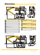
Dimensions E A1 D A W A2 H C K Q T4 M T1 B L U4 B1 B2 Z V X A A1 A2 A3 B B1 B2 C D E H with Yellow Cab H with hydraulic double parallelogram K L M Q T1 T4 U4 Z Industrial-Type Straight Boom 11.50 m and Industrial Stick m V mm W mm X mm mm 3,060 4,440 660 5,000 3,800 6,750 4,700 6,530 4,510 4,590 6,500 6,120 3,940 3,600 1,800 540 1,700 1,775 7,075 8,045 9.00 10.00 9,870 8,750 6,000 6,000 16,850 16,800 Industrial-Type Gooseneck Boom 12.
Industrial Attachment with Industrial-Type Straight Boom 11.50 m ft m 85 26 Attachment Envelope 80 24 Kinematic variants 2A/3B 22 1 with industrial stick 9,00 m 2 with industrial stick 10,00 m 3 with industrial stick 9,00 m and grapple model 72 C 4 with industrial stick 10,00 m and grapple model 72 C 75 70 65 20 60 18 55 50 16 45 14 40 12 35 30 8 20 6 10 5 0 -5 -10 -15 Industrial-type straight boom 11.50 m Industrial stick 9.00 m Grapple model 72 C/1.
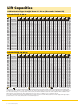
Lift Capacities with Industrial-Type Straight Boom 11.50 m (Kinematic Variant 2A) Industrial Stick 9.00 m 4.5 m 6.0 m 7.5 m 9.0 m 10.5 m 12.0 m 13.5 m 15.0 m 16.5 m 18.0 m 19.5 m 21.0 m m Undercarriage 25.5 4 pt. outriggers down 24.0 4 pt. outriggers down 13.2* 13.2* 22.5 4 pt. outriggers down 13.0* 13.0* 11.2* 11.2* 21.0 4 pt. outriggers down 12.7* 12.7* 11.2* 11.2* 8.9* 8.9* 19.5 4 pt. outriggers down 13.
Lift Capacities with Industrial-Type Straight Boom 11.50 m (Kinematic Variant 3B) Industrial Stick 9.00 m 4.5 m 6.0 m 7.5 m 9.0 m 10.5 m 12.0 m 13.5 m 15.0 m 16.5 m 18.0 m 19.5 m 21.0 m m Undercarriage 25.5 4 pt. outriggers down 24.0 4 pt. outriggers down 13.8* 13.8* 22.5 4 pt. outriggers down 13.3* 13.3* 11.7* 11.7* 21.0 4 pt. outriggers down 11.7* 11.7* 10.7* 10.7* 9.6* 9.6* 19.5 4 pt. outriggers down 11.
Industrial Attachment with Industrial-Type Gooseneck Boom 12.50 m ft m Attachment Envelope 26 80 24 70 Kinematic variant 3D 1 with industrial stick 9,00 m 2 with industrial stick 10,00 m 3 with industrial stick 9,00 m and grapple model 72 C 4 with industrial stick 10,00 m and grapple model 72 C 22 20 60 18 50 16 14 Operating Weight 40 12 30 Operating weight includes basic machine and industrial attachment with: 10 Industrial-type gooseneck boom 12.50 m Industrial stick 9.
Lift Capacities with Industrial-Type Gooseneck Boom 12.50 m (Kinematic Variant 3D) Industrial Stick 9.00 m 4.5 m 6.0 m 7.5 m 9.0 m 10.5 m 12.0 m 13.5 m 15.0 m 16.5 m 18.0 m 19.5 m 21.0 m m Undercarriage 25.5 4 pt. outriggers down 24.0 4 pt. outriggers down 22.5 4 pt. outriggers down 8.9* 8.9* 8.2* 8.2* 21.0 4 pt. outriggers down 8.0* 8.0* 7.5* 7.5* 19.5 4 pt. outriggers down 7.9* 7.9* 7.4* 7.4* 7.
Industrial Attachment with Industrial-Type Gooseneck Boom 11.50 m ft m Attachment Envelope 80 24 70 Kinematic variant 3D 22 1 with industrial stick 9,00 m 2 with industrial stick 10,00 m 3 with industrial stick 9,00 m and clamshell model 22 B 4 with industrial stick 10,00 m and clamshell model 22 B 20 60 18 50 16 14 Operating Weight 40 12 30 Operating weight includes basic machine and industrial attachment with: 10 8 20 Industrial-type gooseneck boom 11.50 m Industrial stick 9.
Lift Capacities with Industrial-Type Gooseneck Boom 11.50 m (Kinematic Variant 3D) Industrial Stick 9.00 m 4.5 m 6.0 m 7.5 m 9.0 m 10.5 m 12.0 m 13.5 m 15.0 m 16.5 m 18.0 m 19.5 m 21.0 m m Undercarriage 25.5 4 pt. outriggers down 24.0 4 pt. outriggers down 22.5 4 pt. outriggers down 8.9* 8.9* 21.0 4 pt. outriggers down 9.0* 9.0* 8.5* 8.5* 19.5 4 pt. outriggers down 8.2* 8.2* 7.9* 7.9* 18.0 4 pt.
D4 Hydraulic Cab Elevation with Double Parallelogram D3 D2 D1 B2 B1 C1 C4 B4 C3 Hydraulic Cab Elevation Parallelogram + Intermediate Piece 0.5 m B1 B2 C1 C2 D1 D2 B2 6,035 mm 9,605 mm 6,530 mm 10,100 mm 2,890 mm 3,040 mm The parallelogram cab raiser allows the operator to choose his field of view between dimensions B1 and B2.
Variety of Tools Shells for Loose Material Cutting width of shells Capacity For loose material, specific weight up to Total weight mm m3 t/m3 kg Multiple Tine Grapples Grapple Model 72 C (4 tines) Grapple Model 72 C (5 tines) Capacity Weight Capacity Weight Clamshell Model 22 1,500 1.85 1.5 2,300 open tines m3 kg m3 kg 1.20 1,970 1.20 2,370 1.40 2,000 1.40 2,410 1.60 2,005 1.60 2,420 Shells for loose material with cutting edge (without teeth) 1,500 2,000 2.20 2.50 1.2 1.
Equipment Undercarriage Two circuit travel brake with accumulator Travel motor protection Outrigger zylinder rod guards Creeper speed electrically switchable from cab New tires Service free parking brake Independent outrigger control Choice of tires Auto check valve directly on each stabilizer cylinder Proportional power steering Customized colors Two lockable storage boxes Two-speed power shift transmission Operator’s Cab • – + • • • • + • • + • – Uppercarriage Electric fuel tank filler pump Maintenance-
Liebherr-Hydraulikbagger GmbH Liebherrstraße 12, D-88457 Kirchdorf/Iller +49 7354 80-0, Fax +49 7354 80-72 94 www.liebherr.com, E-Mail: info.lhb@liebherr.com Seite ist rechts 2 mm schmäler Printed in Germany by Typodruck RG-BK LHB/VF 10424694-2-03.10_enGB All illustrations and data may differ from standard equipment. Subject to change without notice.