Installation Instructions For “NoFrost” Combined Refrigerator-Freezers with IceMaker CS/CBS 20 7084 849-00
Important Please Read and Follow these Instructions Contents These instructions contain Danger, Warning and Caution notes. This information is important for safe and efficient installation and operation. Always read and comply with all Danger, Warning and Caution notes! DANGER! Danger indicates a hazard which will cause serious injury or death if precautions are not followed. Page Unit dimensions.............................................................. 4 Unit venting...............................
Safety Disposal of Old Appliance DANGER! Risk of child entrapment. Child entrapment and suffocation are not problems of the past. Junked or abandoned refrigerators are still dangerous – even if they will sit for “just a few days.” If you are getting rid of your old refrigerator, please follow these instructions to help prevent accidents. Before you discard old appliances: • Take off the doors.
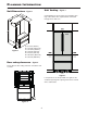
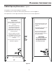
Planning Information Unit Dimensions Unit Venting - Figure 1 - Figure 3 CS 20 appliances do not require any ventilation openings in the cabinet. The required airflow is directed through the toe kick area. Figure 1 A = 3-17/32" (90 mm) B = 79-13/16" (2027 mm) C = 35-13/16" (910 mm) D = 13-9/16" (344 mm) E = 24-7/32" (615 mm) G = 40-13/16" (1037 mm) H = 39-7/16" (1002 mm) Door swing clearence - Figure 2 Please allow for door swing clearance at locations next to a wall.
Planning Information Cabinet Opening Dimensions - Figure 4 The appliance can be used freestanding or semi built-in. If semi built-in, please consider the cabinet opening dimensions as shown in Figure 4. The requirements for water supply and electrical outlet are the same for both applications. IMPORTANT For 24" cabinets, the water line opening must be in the location as shown. This is where the power cord extends from the back of the appliance.
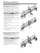
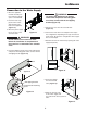
Blocking for Safety Mounting the anti tipping device on concrete floors - Figure 5 - 6 Secure the appliance in place so it does not tip forward when the fully stocked door is opened. The anti tipping bracket is provided with the appliance. 1. Mark the center line of the appliance on the back wall. Align the anti tipping bracket center to this line. Wall Be sure that there is no plumbing or electrical wiring located in this area which screws or drills could damage. Figure 5 2.
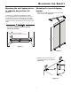
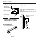
Blocking Mounting the anti tipping device in cabinets deeper than 24" - Figure 8 To ensure the compressor mounting plate reaches the anti tipping bracket at cabinets deeper than 24", a wooden spacer must be mounted between the appliance back and the wall. The anti tipping bracket will be fastened to the floor downwards and to the spacer backwards. for Safety Mounting the top anti-tipping bracket 1. Mount the anti-tipping bracket provided on the wall using 6 x 60 screws (Figure 9).
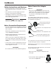
IceMaker Safety Instructions and Warnings Water Connection Adapter • Do not install the water connection while the combined refrigerator-freezer is connected to an electrical outlet. Figure 11 • The connection to the water supply may only be made by a trained and licensed plumber. • All equipment and devices used to supply the water to the appliance must comply with the current regulations for your geographical area.
IceMaker Connection to the Water Supply 1. Move the appliance towards the final position and leave enough space to work behind. WARNING! To prevent the appliance from tipping forward the compressor mounting plate must have contact with the anti tipping bracket (Figure 14). 2. Insert the water supply line into its intended opening at the back of the appliance (Figure 13). 5. Remove the cover from the solenoid valve (Figure 15). 3. Move the power supply line to the area of the electrical outlet.
Installation Leveling the Appliance Adjusting the front of the drawer - Figure 19 - Figure 17 1. The height can be adjusted in front by twisting the leveling feet . If required, the front of the freezer drawers can be adjusted. Transfer the screws shown in the illustration (on the left and right sides of the freezer drawer) individually to the long slots below. Tighten the screws in the front of the drawer once it is in the right position. 1 2.
Installation Mounting the Ventilation Grille - Top Door Hinge Clearance - Figure 22 Figure 20, 21 1. Pull out the bottom freezer drawer. 2. Remove the blue protection film from the dust filter provided and insert the filter into its opening in the toe kick area as shown in Figure 20. Attach the filter at the bottom, press down the button and click into place.
For Service in the U.S. Liebherr Service Center Toll Free: 1-866-LIEBHER or 1-866-543-2437 Email: Service-appliances.us@liebherr.com PlusOne Solutions, Inc. 3501 Quadrangle Blvd, Suite 120 Orlando, FL 32817 For Service in Canada Liebherr Service Center Toll Free: 1-888-LIEBHER or 1-888-543-2437 www.euro-parts.ca EURO-PARTS CANADA 39822 Belgrave Road Belgrave, Ontario, N0G 1E0 Phone: (519) 357-3320 Fax: (519) 357-1326 *708484900* w w w. l i e b h e r r - a p p l i a n c e s .