
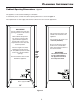
Installation instructions

9
I
ce
m
aker
Figure 15
Figure 16
9. Open the shut-off valve
for the water supply and
check the entire water system for
leaks.
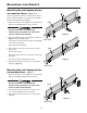
Connection to the Water Supply
1. Move the appliance
towards the final posi-
tion and leave enough
space to work behind.
2. Insert the water sup-
ply line into its inten-
ded opening at the
back of the appliance
(Figure 13).
3. Move the power supply
line to the area of the
electrical outlet.
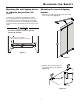
Figure 14
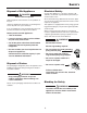
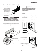
Anti tipping bracket
Compressor mounting
plate
Wall
Appliance
4. Push the appliance slowly to the back wall until the
compressor mounting plate makes contact with the
anti-tipping bracket (Figure 14).
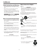
WARNING!
Donotconnecttotheelectricaloutlet
before the installation is completed and
the water line is connected to the solenoid
valve.
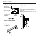
8. Screw the adapter
onto the solenoid
valve (Figure 16).
5. Remove the cover from the solenoid valve
(Figure 15).
6. Connect the water line to the adapter in the respec-
tive configuration, depending on the type of water line
used. Figure 16 shows the configuration with a copper
line as an example.
7. Bleed the air from the water line by opening the water
supply temporarily.
Figure 13
WARNING!
To prevent the appliance from tipping
forward the compressor mounting plate
must have contact with the anti tipping
bracket (Figure 14).