Installation Instructions For Fully Integrated NoFrost Combined Refrigerator-Freezers CS/CBS 20 7084 437-00
Important Please read and follow these instructions Contents Page Planning information Unit dimensions....................................................... 4 Unit venting.............................................................. 4 Cabinet opening dimensions................................... 5 Blocking for safety Mounting the anti tipping device on concrete floors......................................................................... 6 Mounting the anti tipping device on wooden floors............
Installation Guidelines Disposal of old appliance DANGER! Risk of child entrapment. Child entrapment and suffocation are not problems of the past. Junked or abandoned refrigerators are still dangerous – even if they will sit for “just a few days.” If you are getting rid of your old refrigerator, please follow these instructions to help prevent accidents. Before you discard old appliances: • Remove the doors.
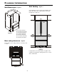
Planning Information Unit Dimensions Unit Venting - Figure 1 - Figure 3 CS 20 appliances do not require any ventilation openings in the cabinet. The required airflow is directed through the toe kick area. Figure 1 A = 3-17/32" (90 mm) B = 79-13/16" (2027 mm) C = 35-13/16" (910 mm) D = 13-9/16" (344 mm) E = 24-7/32" (615 mm) G = 40-13/16" (1037 mm) H = 39-7/16" (1002 mm) Door swing clearence - Figure 2 Please allow for door swing clearance at locations next to a wall.
Planning Information Cabinet Opening Dimensions - Figure 4 The appliance can be used freestanding or semi built-in. If semi built-in, please consider the cabinet opening dimensions as shown in Figure 4. The requirements for water supply and electrical outlet are the same for both applications. IMPORTANT Do not install the shut-off valve behind the appliance. The position of the electrical outlet can be within the grey shaded areas or above the appliance. Water line opening Water supply line A. B. C.
Blocking for Safety Mounting the anti tipping device on concrete floors - Figure 5 - 6 Secure the appliance in place so it does not tip forward when the fully stocked door is opened. The anti tipping bracket is provided with the appliance. 1. Mark the center line of the appliance on the back wall. Align the anti tipping bracket center to this line. Wall Be sure that there is no plumbing or electrical wiring located in this area which screws or drills could damage. Figure 5 2.
Blocking Mounting the anti tipping device in cabinets deeper than 24" - Figure 8 To ensure the compressor mounting plate reaches the anti tipping bracket at cabinets deeper than 24", a wooden spacer must be mounted between the appliance back and the wall. The anti tipping bracket will be fastened to the floor downwards and to the spacer backwards. for Safety Mounting the top anti-tipping bracket 1. Mount the anti-tipping bracket provided on the wall using 6 x 60 screws (Figure 9).
IceMaker Safety Instructions and Warnings • Do not install the water connection while the combined refrigerator-freezer is connected to an electrical outlet. • The solenoid valve has a metric R3/4 male connector. A R3/4 (metric) to a 1/4" OD adapter is supplied with the ice maker. • The connection to the water supply may only be made by a trained and licensed plumber. • All equipment and devices used to supply the water to the appliance must comply with the current regulations for your geographical area.
IceMaker 4. Push the appliance slowly to the back wall until the compressor mounting plate makes contact with the anti tipping bracket (Figure 13). To prevent the appliance from tipping forward the compressor mounting plate must have contact with the anti tipping bracket (Figure 13). Wall Figure 14 Appliance Anti tipping bracket Compressor mounting plate Figure 13 Figure 15 5. Remove the cover from the valve connector (Figure 14). 6. The water line is visible at the front of the aplliance.
Installation Leveling the Appliance Adjusting the front of the drawer - Figure 18 - Figure 16 1. The height can be adjusted in front by twisting the leveling feet . If required, the front of the freezer drawers can be adjusted. Transfer the screws shown in the illustration (on the left and right sides of the freezer drawer) individually to the long slots below. Tighten the screws in the front of the drawer once it is in the right position. 1 2.
Installation Mounting the Ventilation Grille - Top Door Hinge Clearance - Figure 21 Figure 19, 20 1. Pull out the bottom freezer drawer. 2. Remove the blue protection film from the dust filter provided and insert the filter into its opening in the toe kick area as shown in Figure 16. Attach the filter at the bottom, press down the button and click into place.