Installation Instructions For Built-In NoFrost Combined Refrigerator-Freezers 7080-001 C 16 CI 16 7080 007-00
IMPORTANT PLEASE READ AND FOLLOW THESE INSTRUCTIONS These instructions contain Warning and Caution statements. This information is important for safe and efficient installation. Always read and follow all Warning and Caution statements! ! WARNING States a hazard that may cause serious injury or death if precautions are not followed. ! CAUTION Signals a situation where minor injury of product damage may occur if you do not follow instructions.
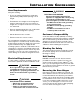
INSTALLATION GUIDELINES Area Requirements ! WARNING Verify the following: ELECTROCUTION HAZARD Electrical Grounding Required. This appliance is equipped with a three-prong (grounding) polarized plug for your protection against possible shock hazards. • DO NOT remove the round grounding prong from the plug. • DO NOT use a two-prong grounding adapter. • DO NOT use an extension cord to connect power to the unit.
PLANNING INFORMATION Cabinet Opening Dimensions = = Allow units to open a minimum of 90° to prevent problems removing drawers. With the door opening 90°, you may have to move drawers slightly to clear the door interior. Electrical outlet location Allow for a minimum 2" (51 mm) filler, for corner installations, so the door can open to 90°. If you’re using raised panels, consider using a wider filler.
PLANNING INFORMATION Unit Dimensions Front view Side view 26" (660 mm) 24" (609 mm) - C 16 24-1/2" (620 mm) - CI 16 maximum height 81-11/16" (2075 mm) minimum height 81 - 1/16" (2059 mm)* Air Vent 22-1/8" (562 mm) Top view 30" (762 mm) 19" (482 mm) ° 90 13 0° 47" (1194 mm) 23-5/16" (592 mm) 29" (737 mm) 52-3/4" (1340 mm) maximum height 84-1/4" (2140 mm) minimum height 83 5/8" (2124 mm)* Optional factory air vent 30" (762 mm) DOOR SWING CLEARANCE 1-13/16" (46 mm) Figure 2 5 * Overall heig
INTEGRATING CABINETRY - CI 16 ONLY Framed Panels If the thickness of the custom panels is less than 1/4" (6.4 mm), they must be backed up with a sheet of shim material to build the total thickness to 1/4" (6.4 mm). The door handles must be installed before the screw covers are installed. If you fail to install the handles before the screw covers, you can damage the covers. The screw covers are taped to the unit doors during shipping. Use care when removing covers. If the panel is thicker than 1/4" (6.
INTEGRATING CABINETRY - CI 16 Overlay Panels ONLY IMPORTANT If you are replacing the factory air vents with an overlay, DO NOT restrict the air flow. The air flow must be the same or greater than the factory air vents of 31 square inches (200 cm²). The overlay design line allows decorative panels to cover the door trim for a more seamless appearance that blends with the design of the room. To achieve this look, the most common way is to work with three panels, the decorative overlay panel, a 3/32" (2.
INTEGRATING CABINETRY - CI 16 ONLY Handle Clearance It is important to provide adequate clearance behind the handle so that the user's hand fits easily. The clearance may not have to be the entire length of the handle, but should be designed for user's comfort. Please note that for framed installations, the optional factory Liebherr handles must be ordered.
INTEGRATING CABINETRY - CI 16 ONLY Frameless cabinets: The casing trim overlaps the cabinets at the side and top. Cabinets may require filler strips to prevent interference with the cabinet door swing. The door opening must allow for filler strips. Door Swing Clearance 130° CI 16 The factory setting for the door to swing open is 130°. Use this illustration to ensure other cabinets or counters do not interfere with the door opening.
INTEGRATING CABINETRY - CI 16 Door Swing Clearance 90° CI 16 ONLY Frameless cabinets: The casing trim overlaps the cabinets at the side and top. Cabinets may require filler strips to prevent interference with the cabinet door swing. The door opening must allow for filler strips. The optional setting for the door to swing open is 90°. Use this illustration to ensure other cabinets or counters do not interfere with the door opening.
INTEGRATING CABINETRY - C 16 Door Swing Clearance 130° C 16 Figure 8 11 ONLY
INTEGRATING CABINETRY - C 16 Door Swing Clearance 90° C 16 Figure 9 12 ONLY
MOUNTING THE UPPER VENTILATION GRILLE IMPORTANT If you are replacing the factory air vents with an overlay, DO NOT restrict the air flow. The air flow must be the same or greater than the factory air vents of 31 square inches (200 cm2). Position the ventilation grille at the top of the installation frame and attach it later with countersunk screws (4 pieces, provided). Make sure the grille fits flush laterally with the installation frame.
BLOCKING FOR SAFETY Figure 12: Secure the appliance in place so it does not tip forward when the fully stocked door is opened. Two anti tipping brackets are included with the unit. 1. Mark the center of the appliance on the back wall. 2. Also mark the install height of the tipping brackets on the back wall .(Min. 3-3/8", Max 4"). 3. Screw the first anti tipping bracket in a wall stud, make sure that it is within the 9-1/2 "(241 mm) right or left from the center line of the appliance.
DOOR STOP ADJUSTMENT Select between two opening angles: 130° and 90°. Your appliance was delivered with a door opening of 130°. If 90° opening angle is required, use this procedure: 2 1. Close the refrigerator door. 2. Turn screw (1), provided, into bore (2). Use the same procedure to set up the freezer door.