Operating instructions NoFrost combined refrigerator-freezer Installation instructions Page 2 Page 16 7084 653-01 ECBN 50
Safety instructions and warnings • In the event that the appliance is damaged on delivery, contact the supplier immediately before connecting to the mains. • Do not store explosives or sprays using combustible propellants such as butane, propane, pentane etc. in the appliance. Electrical components might cause leaking gas to ignite. You may identify such sprays by the printed contents or a flame symbol. • Disconnect the appliance from the mains if any fault occurs.
Description of the appliance 1 Operating and control elements 2 Adjustable door racks 3 Adjustable storage shelves 4 Bottle racks 5 Type plate (behind the vegetable drawer on the left-hand side) 6 Vegetable drawers 7 Water filter 8 Upper freezer drawer 9 Lower freezer drawer blIceMaker (in the interior of the upper freezer drawer) bm Ventilation grille. In this area, the exchange of air for the refrigeration unit takes place.
Range of appliance use The appliance is suitable solely for cooling food in a domestic environment or similar. This includes, for example, use - in staff kitchenettes, bed and breakfast establishments, - by guests in cottages, hotels, motels and other forms of accommodation. The appliance is not intended for commercial use such as in catering and similar services in the wholesale trade. Use the appliance solely as is customary within a domestic environment. All other types of use are inadmissible.
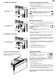
Installing the water filter Switching the appliance on and off EN You are advised to clean the appliance before switching it on for the first time (see "Cleaning"). Do not load with frozen food until the temperature shows at least -18°C. The refrigerator and freezer compartments can be operated separately. 1. Remove the cover of the filter socket. Switching on: touch the On/Off icons (on left for refrigerator, on right for freezer) so that the temperature displays light up or flash.
Audible warning signal The appliance is equipped with an alarm function. Audible door alarm If an appliance door is left open for more than 60 seconds, the audible warning signal will sound. Touch the ALARM icon to cancel the alarm. The alarm switches back to standby when the door is shut. Audible/visual temperature alarm It sounds when it is not cold enough in the freezer compartment. The temperature display and the LED will also flash.
= Sabbath mode EN = Child lock This function complies with the religious requirements to be observed on the Sabbath or religious holidays. The child lock is designed to protect the appliance from being switched off accidentally. When Sabbath mode is activated, some of the functions of the control electronics are switched off. Activating the child lock • The interior light remains switched off if one of the appliance doors is opened.
= Display brightness = Ice maker vacation state See section entitled "Ice maker". Adjusting the display brightness • Activate setup mode by touching the SuperFrost icon for 5 seconds. = Water quantity for ice cube tray If the produced ice cubes of the ice maker are too small, the inflowing water quantity can be adjusted. Adjusting the water quantity • Activate setup mode by touching the SuperFrost icon for 5 seconds. • Touch the freezer compartment Down icon until the display.
EN = Confirm dust filter cleaning Once the dust filter in the appliance plinth has been cleaned, the dust filter LED in the display must be cancelled. Cancelling the dust filter symbol • Activate setup mode by touching the SuperFrost icon for 5 seconds. • Touch the freezer compartment Down icon until the display. appears in Removing the shelves 1. Follow the first three steps in the chapter above. 2. Move the shelf down and stop just over the vegetable drawer. 3.
Interior light The interior light is located at the left, right and top in the refrigerator compartment and above each drawer in the freezer compartment. It comes on if one of the doors or a freezer drawer is opened. Arranging food The light switches off automatically if one of the doors or a freezer drawer has been left open for more than 15 minutes. The audible warning signal sounds at the same time. If one of the strip lights is not lit, it is defective.
EN BioFresh compartment Freezer compartment description The constant temperature of just above 0°C and the adjustable humidity provide the ideal storage conditions for different types of food. The ice cube bin in the upper drawer is intended for ice cubes only. The BioFresh compartment enables you to keep food for up to 3 times longer than in normal refrigerators. The BioFresh compartment satisfies the requirements of a chill compartment to EN ISO 15502.
Notes on freezing • Always store identical food items together. • Pack food which you are freezing yourself in quantities appropriate to your household. To ensure that the food freezes right through, the following quantities should not be exceeded per package: fruit, vegetables: up to 1 kg, meat: up to 2.5 kg.
Switching the ice maker on • Touch the IceMaker icon comes on. so that the IceMaker LED After you start the ice maker for the first time, it may take up to 24 hours before the first ice cubes are ready. The production capacity depends on the temperature inside the freezer compartment. The lower the temperature, the more ice cubes can be produced over a period of time. The ice cubes fall out of the ice maker into the ice cube bin.
Defrosting Cleaning the air filter The refrigerator compartment defrosts automatically. The water that forms on the rear wall drains into a reservoir at the back of the appliance and evaporates automatically through the compressor heat. • Open the bottom freezer drawer and remove the ventilation grille by pulling forwards. The grille is supported magnetically so no tool is required for removing. Refrigerator compartment Freezer compartment The NoFrost system automatically defrosts the appliance.
Removing the freezer drawer containers • Open the refrigerator door. • Pull out the freezer drawer. • Pull the container upwards by the right and left corners (1). • Push the container backwards (2).
Setting up • Avoid positioning the appliance in direct sunlight or near cookers, radiators and similar sources of heat. • The floor on which the appliance stands should be horizontal and level. • Standard EN 378 specifies that the room in which you install your appliance must have a volume of 1 m³ per 8 g of R 600a refrigerant used in the appliance, so as to avoid the formation of inflammable gas/air mixtures in the room where the appliance is located in the event of a leak in the refrigerant circuit.
Installation dimensions Appliance dimensions The location of the socket can within a radius of 2000 mm from the appliance top center. A = 76 mm B = 2027 mm C = 757 mm D = 610 mm E = 1413 mm F = 952 mm This type of dimension line indicates the height measured from the floor. Cabinet depth D 625 mm + panel thickness > Inset installation style 625 mm > Frameless installation style Explanation of "Installation styles" see page 4.
Definition of Inset Installation Style Definition of Frameless Installation Style Appliance and panels sit fully within the opening and are flush with what could be its own box, between two pantry cabinets or decorative columns. With this installation style, these wider appliance panels partially overlay the shared side gables of adjacent cabinetry so as to mimic the look of a frameless style cabinet.
Door swing clearance - Inset Installation Style Right side wall of appliance housing Front of appliance housing Top View Front panel - door closed Panel thickness e= ngl ga nin ope oor l-d ane nt p Fro ° 115 Panel thickness 19
Door swing clearance - Frameless Installation Style Right side wall of appliance housing Front of appliance housing Top View Front panel - door closed Panel thickness e= ngl ga nin ope oor l-d ane nt p Fro ° 115 Panel thickness 20
Mounting the anti-tipping device WARNING! The supplied anti-tipping bracket must be installed in all cases. This prevents the appliance from tipping over when the fully loaded door is opened. Mounting options Mounting the bracket with the wall studs. Mounting with plugs to concrete walls. 3 Screws 6 x 60 mm ll Wa Flo CAUTION! Ensure that there are no electric cables or water pipes in the wall section to which the anti-tipping bracket is to be secured. These could be damaged during installation.
Connection to the water supply Safety instructions and warnings • Do not connect to the water supply while the combined refrigerator-freezer is connected to the electricity supply. • The connection to the mains water supply may only be made by trained personnel. • The water quality must comply with the drinking water directives of the country in which the appliance is used. Installation 1. Place the appliance in front of the installation recess. 2.
5. Locate the water hose into the rail of the appliance base. 8. Push the appliance slowly into the recess until the compressor mounting plate touches the anti-tipping bracket. 5. 8. 6. Route the mains cable towards the socket. 7. Route the water hose towards the water shut-off tap. 9. Fill the hose with water and connect to the shut-off tap. Be sure the connection is tightly arranged. 6. 7. Open the shut-off tap and check the system for leakage.
Leveling the appliance 1. Adjust the height of the appliance at the front by twisting the leveling feet 1. Use the open-ended spanner provided. Turn the spanner counterclockwise to raise the appliance front and clockwise to lower it. ). Position the spanner accordingly( 1 2. Adjust the height of the appliance at the rear by turning the adjusting bolts 2. Use a 1/4" box spanner or the Torx 25 wrench provided. Mounting the ventilation grille Pull out the bottom freezer drawer. 1.
4. The front edge of the brackets is flush with the front of the ventilation grille. Adjust the supports accordingly. 7. Adjust the height of the ventilation grille. • Loosen the grub screws at the front of the grille (Allen key A/F 2.5). • Adjust the ventilation grille to the desired height. • Tighten the grub screws. 4. 7. 5. Insert the locking pins to block the supports. 5. 6. Install the ventilation grille. The grille has bolts on the inside (see detail in the drawing below).
Adjusting the refrigerator door The lateral tilt of the refrigerator door can be adjusted if required. Undo screws 1. Adjust the lateral tilt using the grub screw 2 (Allen key A/F 2.5). Removing the mounting accessories from the refrigerator door Remove the cover 1 and unscrew the top and bottom attachment brackets 2 from the refrigerator door. These attachment brackets will be mounted onto the refrigerator door panel.
Mounting the attachment brackets onto the door panels 1. Draw a line 1041 mm from the bottom side of the door panel. 2. Draw a further line 107.5 mm from the bottom side of the door panel. 3. Align one of the refrigerator door attachment brackets to the top line, as shown in the illustration below, and secure with at least 6 screws (4 x 14). 4. Align the second refrigerator door attachment bracket to the bottom line, as shown in the illustration below, and secure with at least 6 screws (4 x 14). 5.
Mounting the refrigerator panel fig. A 1. Screw in the adjusting pins on the underside of the refrigerator door completely (fig. A). fig. D 6. Adjust the panel horizontally (using the long slots in the attachment bracket) (fig. D). 7. Tighten the securing nuts. 2. Open the refrigerator door and suspend the refrigerator panel on the top adjusting pins (fig. B). 3. Screw securing nuts onto the adjusting pins and slightly tighten. fig. E 8.
Mounting the freezer panels 10. Undo the three screws on the top of the attachment bracket, adjust the door panel as displayed in fig. G and then retighten the screws. The same procedure can be carried out for the bottom attachment bracket. 1. Pull out the top freezer drawer and screw on the pre-assembled panel. The same screws must be used as those used to screw on the attachment brackets (3.5 x 13). 2. Close the freezer drawer and check the position of the panel.
Liebherr Hausgeräte Lienz GmbH * Dr.-Hans-Liebherr-Strasse 1 * A-9900 Lienz ** www.liebherr.