Installation Instructions For Fully Integrated NoFrost Combined Refrigerator-Freezers HC 1540/1541 7084 331-00
Important Please Read and Follow these Instructions These instructions contain Danger, Warning and Caution notes. This information is important for safe and efficient installation and operation. Always read and comply with all Danger, Warning and Caution notes! DANGER! Danger indicates a hazard which will cause serious injury or death if precautions are not followed. WARNING! Warning indicates a potentially hazardous situation which, if not avoided, could result in death or serious injury.
Safety Disposal of Old Appliance DANGER! Risk of child entrapment. Child entrapment and suffocation are not problems of the past. Junked or abandoned refrigerators are still dangerous – even if they will sit for “just a few days.” If you are getting rid of your old refrigerator, please follow these instructions to help prevent accidents. Before you discard old appliances: • Remove the doors. • Leave the shelves in place so that children may not easily climb inside.
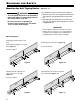
Planning Information Unit Dimensions - Figure 1, Figure 2 Door Swing Clearance - Figure 3 Please allow for door swing clearance at locations next to a wall. The illustrated measurement is without mounted front panels. Be sure to add your panel thickness and handle depth to this measurement in order to avoid interferences.
Planning Information Cabinet Opening Dimensions Cabinet Height Inset cabinet Depth D - Figure 5 Frameless/faceframe cabinet Depth D 80" 24" + panel thickness 24" 84" 24" + panel thickness 24" 1 For appliance with panel to be flush, adjacent cabinetry depth must equal appliance depth (24") plus panel thickness (5/8" - 3/4"). 1 This is where the power cord extends from the back of the appliance.
Planning Information Panel Dimensions - Inset Installation Style - Figure 6 Side view of cabinet Cabinet frame Appliance and panels sit fully within the opening and are flush with what could be its own box, between two pantry cabinets or decorative columns, etc. This is the most common installation scenario. Door panel You can order stainless steel panels for inset installation style.
Planning Information Panel Dimensions - Frameless Installation Style - Figure 7 Side view of cabinet With this installation style, these wider appliance panels partially overlay the shared side gables of adjacent cabinetry so as to mimic the look of a frameless style cabinet.
Blocking for Safety Mounting the Anti Tipping Device WARNING! • The anti tipping bracket must be mounted to prevent the appliance from tipping when the fully stocked door is opened. • Be sure that there is no plumbing or electrical wiring located in this area which screws or drills could damage. - Figures 8 - 11 The anti tipping bracket is provided with the appliance. 1. Mark the center line of the appliance on the back wall. Align the anti tipping bracket center to this line. 2.
Blocking Cover Strips Mounting the Anti Tipping Device in Cabinets deeper than 24" - Figures 12 - 13 A proper function of the anti tipping bracket is warranted within a cabinet depth of between 24" and 25". If the cabinet is deeper than 25", a wooden spacer must be mounted between appliance and wall. WARNING! Be sure the wooden spacer is fastened securely to the floor. for Safety - Figure 14 Apply cover strips above, between and below the securing plates on the side walls of the appliance.
Installation Leveling the Appliance - Figure 16 1. Adjust the height of the appliance at the front by twisting the leveling feet . Use the open-ended spanner provided. Turn the spanner counterclockwise to raise the appliance front and clockwise to lower it. Position the spanner accordingly (Figure 16 - ). 1 1 Fastening the Appliance in the Recess - Figure 17 Fasten the appliance in the recess through the premounted securing plates at left and right on the appliance housing using screws 4 x 16 mm.
Installation Adjusting the Refrigerator Door - Figure 18 Adjusting the Drawer Front - Figure 19 IMPORTANT Under normal conditions, the factory adjustment of the refrigerator door should not be changed. Only if heavy loading of the refrigerator door is expected, may the adjustment be changed. . Adjust the lateral tilt using the grub Undo screws screw (Allen key A/F 2.5). 1 2 If required, the front of the freezer drawers can be adjusted.
Installation Mounting the Ventilation Grille 1. Pull out the bottom freezer drawer. 2. Remove the blue protection film from the dust filter provided and insert the filter into its opening in the toe kick area as shown in Figure 20. Engage the filter at the bottom, press down the button and click into place. 4. Insert the supports for the ventilation grille on the left and right sides in the motor compartment (Figure 22). Figure 22 Figure 20 3. Remove the locking pins of both supports.
Installation Before Mounting the Door Panels - Figures 27, 28 7. Install the ventilation grille (Figure 25). The grille has bolts on the inside (see detail in Figure 25 a). These bolts must be inserted into the holes of the supports. Remove cover 1 and unscrew the upper and lower attachment bracket 2 of the refrigerator door. These brackets will be mounted onto the refrigerator door panel. iMPORTANT The nuts are needed to fit the premounted panel onto the refrigerator door. Figure 25 Figure 25 a 8.
Installation Mounting the Attachment Brackets onto the Door Panels - Figure 29 Mark a line with a distance of 41" and 4-1/4" from the bottom of the refrigerator door panel. Align one of the dismounted brackets of the refrigerator door to the line on the refrigerator door panel as shown in Figure 29 a. Fasten the bracket with any hole wherever possible using a minimum of 6 screws 4 x 16 mm.
Installation Mounting the Refrigerator Door Panel 1. Turn in the adjusting bolts on the bottom of the refrigerator door as far as possible (Figure 30). 4. Close the door and check the height of the panel. 5. Align the panel in its vertical position if necessary. Loosen the hex nuts and turn the adusting bolts (Figure 32). Figure 30 Figure 32 2. Open the refrigerator door and hang the panel on the top adjusting bolts (Figure 31). 6.
Installation 8. Turn the adjusting bolts (bottom refrigerator door) until they make contact with the attachment bracket (Figure 34). 10. Loosen the three screws on the top of the attachment bracket, align the panel as shown in Figure 36 and tighten the screws. This can also be done with the lower attachment bracket. Figure 36 Figure 34 9. Screw on the hex nuts and tighten (Figure 35). 11. Click cover into place. Insert the cover strip provided between refrigerator door and panel (Figure 37).
Installation Mounting the Freezer Drawer Panels - Figure 38 1. Pull out the upper freezer drawer and screw on the panel with three screws on the left and right sides using the screws as shown in Figure 38. 2. Close the drawer and check the position to the surrounding cabinet panels. Align the panel in vertical direction by loosening the screws left and right. Finally tighten the screws. IMPORTANT Do not overtighten. Do not use a power driver. 3.
For Service in the U.S. Liebherr Service Center Toll Free: 1-866-LIEBHER or 1-866-543-2437 Email: Service-appliances.us@liebherr.com PlusOne Solutions, Inc. 3501 Quadrangle Blvd, Suite 120 Orlando, FL 32817 For Service in Canada Liebherr Service Center Toll Free: 1-888-LIEBHER or 1-888-543-2437 www.euro-parts.