Installation Instructions For Fully Integrated NoFrost Combined Refrigerator-Freezers HC 2080/2081 HCB 2080/2081 7084 851-00
Important Please Read and Follow these Instructions Contents These instructions contain Danger, Warning and Caution notes. This information is important for safe and efficient installation and operation. Always read and comply with all Danger, Warning and Caution notes! DANGER! Danger indicates a hazard which will cause serious injury or death if precautions are not followed. WARNING! Warning indicates a potentially hazardous situation which, if not avoided, could result in death or serious injury.
Safety Disposal of Old Appliance DANGER! Risk of child entrapment. Child entrapment and suffocation are not problems of the past. Junked or abandoned refrigerators are still dangerous – even if they will sit for “just a few days.” If you are getting rid of your old refrigerator, please follow these instructions to help prevent accidents. Before you discard old appliances: • Take off the doors. • Leave the shelves in place so that children may not easily climb inside.
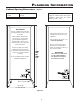
Planning Information Unit Dimensions Unit Venting - Figure 1 - Figure 3 HC 2080/2081 appliances do not require any ventilation openings in the cabinet. The required airflow is directed through the toe kick area. Figure 1 A = 3" (76 mm) B = 79-13/16" (2027 mm) C = 35-13/16" (910 mm) D = 24" (610 mm) E = 61-1/4" (1556 mm) F = 37-1/8" (943 mm) Door Swing Clearance - Figure 2 Please allow for door swing clearance at locations next to a wall. The illustrated measurement is without mounted front panels.
Planning Information Cabinet Opening Dimensions Inset cabinet Depth D - Figure 4 Frameless/faceframe cabinet Depth D 24" + panel thickness For appliance with panel to be flush, adjacent cabinetry depth must equal appliance depth (24") plus panel thickness (5/8" - 3/4"). 24" IMPORTANT For 24" cabinets, the water line opening must be in the location as shown. This is where the power cord extends from the back of the appliance.
Planning Information Panel Dimensions - Inset Installation Style Appliance and panels sit fully within the opening and are flush with what could be its own box, between two pantry cabinets or decorative columns, etc. This is the most common installation scenario. - Figure 5 The panels should be at least 5/8 inch (16 mm) thick to allow the connecting rails to be fastened to them. IMPORTANT The maximum panel thickness is 3/4" (19 mm). The door panel weight must not exceed 60 lb (27 kg).
Planning Information Panel Dimensions - Frameless Installation Style With this installation style, these wider appliance panels partially overlay the shared side gables of adjacent cabinetry so as to mimic the look of a frameless style cabinet. - Figure 6 The gap between panels with frameless installation style is 1/4" (6 mm). The panels should be at least 5/8 inch (16 mm) thick to allow the connecting rails to be fastened to them. IMPORTANT The maximum panel thickness is 3/4" (19 mm).
Blocking for Safety Mounting the Anti Tipping Device on Concrete Floors - Figure 7 - 8 Secure the appliance in place so it does not tip forward when the fully stocked door is opened. The anti tipping bracket is provided with the appliance. Wall 1. Mark the center line of the appliance on the back wall. Align the anti tipping bracket center to this line. Be sure that there is no plumbing or electrical wiring located in this area which screws or drills could damage. Figure 7 2.
Blocking for Safety Mounting the Anti Tipping Device in Cabinets deeper than 24" - Figure 10 - 11 Cover Strips To ensure the compressor mounting plate reaches the anti tipping bracket in cabinets deeper than 24", a wooden spacer must be mounted between the appliance back and the wall. The anti tipping bracket will be fastened to the floor downwards and to the spacer backwards. Cut the cover strips to the length shown in Figure 12.
IceMaker Safety Instructions and Warnings Water Connection Adapter • Do not install the water connection while the combined refrigerator-freezer is connected to an electrical outlet. Figure 13 • The connection to the water supply may only be made by a trained and licensed plumber. • All equipment and devices used to supply the water to the appliance must comply with the current regulations for your geographical area.
IceMaker Connection to the Water Supply 1. Move the appliance towards the final position and leave enough space to work behind. WARNING! To prevent the appliance from tipping forward the compressor mounting plate must have contact with the anti tipping bracket (Figure 16). 2. Insert the water supply line into its intended opening at the back of the appliance (Figure 15). 5. Remove the cover from the solenoid valve (Figure 17). 3. Move the power supply line to the area of the electrical outlet.
Installation Leveling the Appliance Adjusting the refrigerator door - Figure 19 - Figure 21 1. Adjust the height of the appliance at the front by twisting the leveling feet (A/F 27). Use the open-ended spanner provided. The lateral tilt of the refrigerator door can be adjusted if required. Undo screws . Adjust the lateral tilt using the grub screw (Allen key A/F 2.5). 1 1 2 2. Adjust the height of the appliance at the rear by turning the adjusting . bolts 2 3.
Installation Adjusting the front of the drawer - Figure 22 Before Mounting the Door Panels If required, the front of the freezer drawers can be adjusted. Remove cover and unscrew the upper and lower attachment bracket of the refrigerator door. These brackets will be mounted onto the refrigerator door panel. Transfer the screws shown in the illustration (on the left and right sides of the freezer drawer) individually to the long slots below.
Installation Mounting the Attachment Brackets onto the Door Panels - Figure 25 Mark a line with a distance of 41" and 4-1/4" from the bottom of the refrigerator door panel. Align one of the dismounted brackets of the refrigerator door to the line on the refrigerator door panel as shown in Figure 25 a. Fasten the bracket with any hole wherever possible using a minimum of 6 screws 4 x 16 mm.
Installation Mounting the Refrigerator Door Panel 1. Turn in the adjusting bolts on the bottom of the refrigerator door as far as possible (Figure 26). 4. Close the door and check the height of the panel. 5. Align the panel in its vertical position if necessary. Loosen the hex nuts and turn the adusting bolts (Figure 28). Figure 26 Figure 28 2. Open the refrigerator door and hang the panel on the top adjusting bolts (Figure 27). 6.
Installation 8. Turn the adjusting bolts (bottom refrigerator door) until they make contact with the attachment bracket (Figure 30). 10. Loosen the three screws on the top of the attachment bracket, align the panel as shown in Figure 32 and tighten the screws. This can also be done with the lower attachment bracket. Figure 32 Figure 30 11. Click cover 9. Screw on the hex nuts and tighten (Figure 31). 1 into place. Insert the cover strip provided tor door and panel (Figure 33).
Installation Mounting the Freezer Drawer Panels - Figure 34 1. Pull out the upper freezer drawer and screw on the panel with three screws at left and right hand side using the screws as shown in Figure 34. 2. Close the drawer and check the position to the surrounding cabinet panels. Align the panel in vertical direction by loosening the screws left and right. Finally tighten the screws. Mounting the Ventilation Grille - Figure 35, 36 1. Pull out the bottom freezer drawer. 2.
For Service in the U.S. Liebherr Service Center Toll Free: 1-866-LIEBHER or 1-866-543-2437 Email: Service-appliances.us@liebherr.com PlusOne Solutions, Inc. 3501 Quadrangle Blvd, Suite 120 Orlando, FL 32817 For Service in Canada Liebherr Service Center Toll Free: 1-888-LIEBHER or 1-888-543-2437 www.euro-parts.ca EURO-PARTS CANADA 39822 Belgrave Road Belgrave, Ontario, N0G 1E0 Phone: (519) 357-3320 Fax: (519) 357-1326 *708485100* w w w. l i e b h e r r - a p p l i a n c e s .