Installation Instructions Refrigerators and freezers for integrated use, door-on-door HRB 1120 / HF 861 20191127 7088232 - 00
General safety information Contents fume extraction in kitchen units” (see 8 Air circu- 1 General safety information........................... 2 2 Transporting the appliance........................... 2 3 Setting up the device..................................... 2 4 Appliance dimensions................................... 4 5 Recess dimensions....................................... 4 6 Cabinet door...................................................
Setting up the device WARNING Risk of fire due to refrigerant. The refrigerant contained within the appliance is environmentally friendly, but flammable. Leaking refrigerant can ignite. u Do not damage the pipes of the refrigerant circuit. WARNING Danger of fire and damage! u Do not place devices that give off heat, e.g. microwaves, toasters, etc. on the appliance.
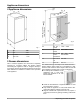
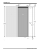
Appliance dimensions 4 Appliance dimensions Fig. 2 in. Fig. 1 in. mm A 22 559 B 21 7/16 544 C 69 11/16 1770 5 Recess dimensions This is a built-in appliance and is therefore completely enclosed by a kitchen cabinet The kitchen cabinet surrounding the appliance must be designed exactly in accordance with the specified fitting dimensions and must allow sufficient air circulation to ensure correct operation of the appliance. mm D 69 3/4 — 1772 — 1788 70 3/8 E 22 22 3/4 F min. 21 5/8, min.
Cabinet door u Ensure that the floor and the side panels of the cabinet are at right angles to each other. - The cabinet door must be assembled flat and free from tension. 6 Cabinet door NOTICE An excessively heavy unit door can cause potential damage! If the unit door is too heavy, we cannot rule out damage to the hinges, which may compromise the use of the unit. u Before installing the unit door, ensure the door does not exceed the permissible weight. - A door is required for the kitchen cabinet.
Cabinet door Fig.
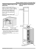
Kitchen cabinet setup for the water filter* 7 Kitchen cabinet setup for the water filter* 8 Air circulation in the kitchen cabinet The water filter module is supplied with the appliance. It should be installed near the appliance in the cabinet, for example in the adapter cabinet above the appliance. To connect the filter to the appliance, it may be necessary to make an opening (C) in the floor of the adapter cabinet through which the hoses will be routed.
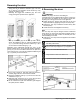
Reversing the door - There must be an effective ventilation gap of at least 31 in2 (200 cm2) per appliance for the air inlet Fig. 6 (A) and the air outlet Fig. 6 (B). - Basically, the bigger the ventilation gap, the more energy-saving the operation of the appliance. Fig. 7 9 Reversing the door WARNING Risk of bodily injury due to the door falling off. If the fasteners are not installed with the proper torque, the door may fall off.
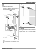
Reversing the door CAUTION Risk of injury if soft stop contracts! u Carefully remove soft stop damper. u Removing the soft stop damper: Remove the soft stop damper from the ball stud (1). Unscrew the retainer (2). Remove the ball stud with a screwdriver (3). Fig. 12 CAUTION Hinges are spring-loaded and can cause pinching injuries! u Leave hinges open. u Removing the door: Push the door forward and then out, unhook it and put it to one side. Fig. 11 u Remove covers.
Reversing the door Fig. 15 u Fitting the door again: Reattach the door to the hinges and tighten the screws. Fig. 13 u Swap the hinges. Fig. 16 u Re-attaching the soft stop mechanism: Screw in the ball studs (1), tighten the retainer (2) and attach the soft stop dampers into the ball studs. Fig. 14 u Swap the fixing bracket to the opposite side.
Water connection* - Use a 1/4"-OD copper wire to connect the water supply with the solenoid valve. This is not supplied with the appliance. - If your model has an IceMaker, a coupler is supplied between the metric R3/4 connection thread and the 1/4"-OD copper wire. Fig. 17 u Check all screws and retighten if necessary. u Fit the bottom left cover again. Only fit the other covers again after installing the appliance into the cabinet again.
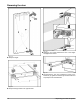
Installing the appliance in the recess. The following accessories are available from Customer Services for installing the appliance in a recess: Set to fit divided cabinet fronts Set with covers for top hinges There is the risk of injury when doing this. Obey the safety instructions. Fig. 19 u Affix the water supply Fig. 19 (7) to the housing, if necessary, using the locking element Fig. 19 (10). Before fitting into the cabinet: u Check the whole water system for leaks.
Installing the appliance in the recess. Fig. 22 If the depth of the unit is less than 21-3/4 in. (553 mm) remove the spacers on the back of the appliance in order to be able to push the appliance completely into the recess. Removing the spacers may cause the appliance to use more energy as this reduces the ventilation cross-section. u Undo the screw and remove the spacers. For appliances with a water filter:* Fig. 20 The following tool is supplied with the appliance: Fig.
Installing the appliance in the recess. Fig. 25 u Remove the top left cover and screw the fixing bracket in loosely. Fig. 26 u Take off cover. Fig. 27 u Assemble the mounting bracket. If the door is large use two pairs of mounting brackets. After assembly, fold the covers onto the bracket. Fig. 28 Fig. 29 With 5/8 in. (16 mm) thick cabinet side panels: u clip spacers on all hinges.
Installing the appliance in the recess. Fig. 30 The width of the equalizer trim is 22 1/2 in. (572 mm). With a 22 in. (560 mm) wide recess: u cut the equalizer trim on both sides with a knife to fit the groove. With a recess width of between 22 in. (560 mm) and 22 1/2 in. (572 mm): u cut the equalizer trim on the hinge side with a knife to fit the groove. With a recess width of 22 1/2 in. (572 mm) to 22 3/4 in. (578 mm): u Use the equalizer trim in its condition when delivered, do not shorten it. Fig.
Installing the appliance in the recess. Fig. 35 u If necessary align the appliance using the adjusting feet. Fig. 34 u Push the appliance in until the handle side above the bracket and below the stop meets the front of the cabinet side panel. With 5/8 in. (16 mm)thick cabinet side panels the spacers on the hinge side must abut at the same time. With 5/8 in. (16 mm) thick cabinet side panels align the front edges of the hinges so that they are flush with the front of the cabinet side panel. Fig.
Installing the appliance in the recess. Fig. 38 u Remove the stop from the bracket on the handle side and dispose of it. Re-attach cover. u Re-attach the cover on the hinge side. u Break the stop at the bottom of the handle side off and dispose of it. Fitting the cover. Fig. 37 u Fix the appliance in the recess, first of all the top hinge side then the bottom. Then handle side down and finally handle side up. * Depending on model and options Fig.
Installing the appliance in the recess. Fig. 40 u Close the door. u Check the default setting of 5/16 in. (8 mm). u Raise fitting aids to unit door height. Bottom stop edge of the fitting aid = top edge of the door to be fitted. Fig. 43 With a 22 3/4 in. (578 mm) wide recess: u align the crosspiece to the middle of the door and then 3/16 (5.5 mm) move towards the hinge side. u With chipboard doors fit the crosspiece with at least 6 screws and at least 4 screws for frame and panel doors. Fig.
Installing the appliance in the recess. Fig. 46 u Attach the unit door and loosely screw the lock nuts onto the adjusting bolts. Fig. 48 u Check the gap between the door and the surrounding unit doors Fig. 49 u Open the cover again to assemble the mounting bracket on the unit door. Align the front edge of the mounting bracket parallel to the unit door edge and screw the bracket down tightly. Fig. 47 u Align the unit door in the X and Y direction using the adjusting bolts. u Tighten the lock nuts.
Installing the appliance in the recess. Fig. 51 u Check the distance between the unit door and the unit body. u Check all screws and retighten if necessary. Fig. 52 u Clip the top cover on. Fig. 53 u Fold the cover onto the mounting bracket. Fig. 54 Check the following points to make sure the appliance is installed correctly. Otherwise, icing up, the formation of condensate and malfunctions may occur: w The door must close properly.
Installing the water filter* w The unit door must not touch the body of the unit. w The seal on the upper corner on the handle side must be fitted securely. To verify this, darken the room, place a flashlight in top part of the appliance and close the door. If you see light shining out, check the assembly. 12 Installing the water filter* The water filter guarantees optimal water quality and should be installed the first time you use the appliance.
Disposal of packaging Fig. 58 u Insert the water filter Fig. 58 (6) and turn it approximately 100° to the right until it locks into position. u Place the cover Fig. 58 (2) on the filter. u Slide the tray in. u Write the date of the next filter replacement on the supplied adhesive label Fig. 58 (9) and affix it to the module. u Make sure the filter is leak-tight and no water is coming out. Note New water filters may contain particulate matter.
Connecting the appliance * Depending on model and options 23
For Service in the U.S.: Liebherr Service Center Toll Free: 1-866-LIEBHER or 1-866-543-2437 Service-appliances.us@liebherr.com PlusOne Solutions, Inc. 3501 Quadrangle Blvd, Suite 120 Orlando, FL 32817 For Service in Canada: Liebherr Service Center Toll Free: 1-888-LIEBHER or 1-888-543-2437 www.euro-parts.ca EURO-PARTS CANADA 39822 Belgrave Road Belgrave, Ontario, N0G 1E0 Phone: (519) 357-3320 Fax: (519) 357-1326 www.liebherr-appliances.com Part No.