Technical data Hydraulic crawler crane HS 8100 HD
Dimensions Basic machine with undercarriage 7600 2900 1220 1360 1150 2680 5360 350 75 3400 63 3500 1950 R 800 1500 6450 4950 00 7 4950 R4 11910 Operating weight Remarks The operating weight includes the basic machine with HD undercarriage, 2 main winches 250 kN including wire ropes (90 m) and 11 m main boom, consisting of A–frame, boom foot (5.5 m) and boom head (5.5 m), 26.3 t basic counterweight, 800 mm 3-web grousers and 50 t hook block. 1.
Transport dimensions and weights Basic machine and boom (No. 1311.22) Basic machine 3180 800 11800 1800 350 with HD undercarriage, boom foot (No. 1311.22), A-frame, 2x 250 kN winches including wire ropes (90 m), without basic counterweight Width 3500 mm Weight 59550 kg Basic machine 3180 870 11800 3040 with boom foot (No. 1311.
Transport dimensions and weights Counterweight Counterweight 6x 475 960 1220 option Width Weight 850 mm 1500 kg Counterweight 1 x Width Weight 3500 840 Carbody counterweight 1050 mm 17330 kg option Width Weight 1960 10 x 2 x 1640 mm 7500 kg Hooks 100 t hook block - 2 sheaves 1150 Width Weight 320 mm 1200 kg 1910 50 t hook block - 1 sheave 900 Width Weight 400 mm 900 kg 1910 40 t hook block - 1 sheave 940 Width Weight 250 mm 515 kg 1910 25 t single hook 400 980 350 880 4 HS 8100
Technical description Engine Main winches Power rating according to ISO 9249, 390 kW (523 hp) at 1700 rpm Engine type Liebherr D 856 A7 SCR Fuel tank 790 l capacity with continuous level indicator and reserve warning Engine complies with NRMM exhaust certification EPA / CARB Tier 4i or 97/68 EC Stage III B. ECO-Silent-Mode: For work not requiring high engine power, the diesel engine can be operated in the ECO-Silent-Mode (e.g.
Equipment (26.3 t counterweight) Casing oscillator and slurry wall grab Boom 1311.22 Casing oscillator* Winch options Line speed 1st layer (m/min) Drilling diameter Slurry wall grab* 2 x 200 kN 0-101 2000 mm *) Load chart for duty cycle operation see page 8 6 HS 8100 HD Boom 1311.22 2 x 250 kN 0-87 2000 mm Winch options Line speed 1st layer (m/min) Max.
Equipment (26.3 t counterweight) Dynamic soil compaction Boom 1313.24 Capacities in metric tonnes for boom lengths (21 m - 33 m) Boom length (m) Radius 21 24 27 30 33 (m) t t t t t 8 25 25 20 20 19 9 20 19 19 18 17 Boom 1311.22 Capacities in metric tonnes for boom lengths (20 m - 32 m) Boom length (m) Radius 20 23 26 29 32 (m) t t t t t 8 25 25 20 20 19 9 20 19 19 18 17 Max. capacities in metric tonnes do not exceed 75% of tipping load. All loads given are max. values and must not be exceeded.
Load chart for duty cycle operation (main boom No. 1311.22) 26.3 t counterweight Capacities in metric tonnes for boom lengths (11 m - 32 m) Counterweight 26.3 t Boom length (m) Radius (m) 4.2 5 6 7 8 9 10 12 14 16 18 20 22 24 26 28 30 11 t 14 t 17 t 20 t 23 t 26 t 37.9 37.7 34.4 28.9 24.5 37.9 37.9 33.5 28.5 24.0 17.9 15.0 37.9 36.5 33.0 27.6 23.3 17.6 14.8 12.7 37.6 36.0 32.1 27.1 22.6 17.3 14.4 12.4 10.8 9.6 37.9 37.9 34.6 30.6 26.1 22.1 16.9 14.1 12.1 10.6 9.3 8.3 34.6 34.6 34.4 28.9 25.
Dragline equipment (main boom No. 1311.22) 26.3 t counterweight Capacities in metric tonnes for boom lengths (14 m - 29 m) counterweight 26.3 t Boom length (m) C 14 alpha 45 40 35 30 25 J C J 17 C J 20 C 23 J (m) (m) t (m) (m) t (m) (m) 11.9 11.4 18.0 14.1 13.5 14.7 16.2 15.6 12.7 10.4 16.8 15.0 12.4 13.6 17.3 14.3 13.4 9.4 15.7 15.9 11.2 12.8 18.3 12.9 14.0 8.4 15.0 16.6 9.9 12.1 19.2 11.4 14.5 7.3 14.4 17.3 8.5 11.6 20.0 9.8 C t 12.3 11.3 10.6 10.0 9.6 (m) 18.3 19.6 20.8 21.8 22.
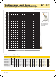
Working range - main boom 86° – 15° (No. 1311.22) 26.3 t counterweight and 15 t carbody counterweight ft 220 m 72 68 180 ° 60 60 ° 50 56 68 52 * m 65 48 2000 * m 62 140 59 m 56 40 44 m 53 40 m 50 m 47 36 100 30 32 m 44 ° 120 The maximum capacity of the auxiliary jib is 25 t. The corresponding load chart is programmed in the LMI system.
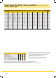
Load chart for lift crane operation (main boom No. 1311.22) 26.3 t counterweight Capacities in metric tonnes for boom lengths (11 m - 62 m) - with 250 kN winches and 26.3 t counterweight Boom length (m) Radius (m) 3.8 4 5 6 7 8 9 10 12 14 18 20 22 26 28 30 32 34 36 38 40 42 44 11 t 57.9 47.4 38.8 32.7 28.2 20.6 14 t 55.0 45.7 39.0 32.9 28.4 22.0 17.9 17 t 20 t 23 t 26 t 52.3 43.8 37.5 32.8 28.4 22.1 18.0 12.6 61.2 49.9 41.9 36.1 31.6 28.1 22.1 18.0 12.7 10.9 58.0 47.6 40.3 34.8 30.6 27.2 22.
Working range - fixed jib 15° and 30° (No. 0806.
Load chart - fixed jib (No. 0806.xx) Offset 15° Main boom 20 m Main boom 11 m Radius (m) 4.7 9 12 14 15 16 18 19 20 28 34 40 11 t 29.4 20.9 17.5 16.1 15.8 15.5 14.8 14.3 13.9 Fixed jib length (m) 20 26 32 t t t 13.5 11.7 10.9 10.6 10.4 9.6 9.3 9.0 7.0 7.5 6.8 6.6 6.4 6.0 5.8 5.7 4.5 4.1 4.9 4.7 4.6 4.4 4.4 4.3 3.8 3.4 3.1 11 t 20.9 16.1 14.9 13.7 13.0 10.4 8.2 6.6 5.3 4.8 Fixed jib length (m) 20 26 32 t t t 10.6 10.0 8.7 7.5 6.6 5.7 5.1 4.6 4.4 3.6 6.9 6.4 5.7 5.0 4.5 3.9 3.5 3.4 2.9 2.7 4.5 4.
Load chart - fixed jib (No. 0806.xx) Offset 30° Main boom 20 m Main boom 11 m Radius (m) 7.4 14 18 20 22 24 28 30 32 36 38 42 11 t 20.4 12.9 11.0 10.4 Fixed jib length (m) 20 26 32 t t t 8.4 7.1 6.6 6.2 5.9 5.3 5.2 5.4 5.1 4.9 4.6 4.1 4.0 3.8 3.6 3.7 3.5 3.2 3.1 2.9 2.7 2.6 2.5 11 t 14.8 11.7 11.1 9.4 8.9 7.5 6.0 5.4 4.9 Fixed jib length (m) 20 26 32 t t t 6.0 5.5 5.0 4.8 4.4 4.0 3.9 3.8 3.7 3.3 4.1 3.7 3.6 3.3 3.1 2.9 2.8 2.6 2.5 2.5 2.9 2.8 2.6 2.4 2.3 2.2 2.0 Main boom 50 m Radius (m) 10.
Self-assembly system Unloading of basic machine (option) Unloading and assembly of crawlers Unloading of basic machine (standard) Unloading and assembly of carbody counterweight Unloading and assembly of boom Unloading and assembly of counterweight Assembly of boom and reeving of hoist ropes HS 8100 HD 15
HS 8100 HD – 10098997 – 03/2013 Subject to change without notice. Liebherr-Werk Nenzing GmbH Dr. Hans Liebherr Str. 1, 6710 Nenzing/Austria Tel.: +43 50809 41–473, Fax: +43 50809 41–499 crawler.crane@liebherr.com, www.liebherr.com facebook.