Hydraulic Diaphragm Wall Grab Mechanical Diaphragm Wall Grab Stop End Pipes Hydraulic Tube Extracting Equipment Interlocking Tremie Pipes
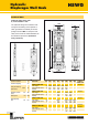
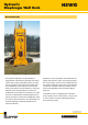
HSWG Hydraulic Diaphragm Wall Grab Technical Data Hydraulic tilting of the grab X, Y and rotation ± 100° 2200 The hydraulic tilting with inclination measuring and monitoring of the operator's cabin guarantees a verticality of the diaphragm wall of 1:800. To certify the verticality of the trench the measured data can be stored and printed out. (Patents in many countries). 800 ~8200 ~8750 800 2.8 or 3.2 Inclination detection x,y Inclination adjusting ±2° Lifting and lowering speed (max.
Hydraulic Diaphragm Wall Grab HSWG General Remarks The hydraulic diaphragm wall grab HSWG is equipped with a permanent measuring and control system which makes it possible primarily to recognize any deviation of the vertical excavating direction immediately, and to indicate it to the control panel of the operator and secondarily to correct any deviation of the vertical position by means of a modification of the direction of the grab.
SWG Diaphragm Wall Grab SWG 2.8 (3.4)-5/400-600 2300 395 2450 400/500/600 8900 10000 2800 (max. 3400) Width of diaphragm wall mm 400 Width of basic body Jaw capacity (2800 mm) (approx.) Jaw capacity (3400 mm) (approx.) Quantity of pulleys Weight (approx.
Diaphragm Wall Grab SWG General Remarks Jaws of angular or round shape are available. The jaws, ropes and rope pulleys can quickly be replaced on site without any problem. The teeth are replaceable. Light chiseling work is possible. All rope and guide pulleys have adequatley dimensioned, maintenance-free bearings filled with oil.
SWG Diaphragm Wall Grab SWG 2.8 (3.3)-6/600-1000 575 2200 2000 3800 10975 Removable extension piece 12000 2390 600/800/1000 2800 (max. 3300) Width of diaphragm wall mm Width of basic body Jaw capacity (approx.) Quantity of pulleys Weight with extension piece (approx.) Weight without extension piece (approx.
SWG Diaphragm Wall Grab SWG 2.8-5/500-800 2000 495 2000 3800 Removable extension piece 10000 2390 2800 500/600/800 Width of diaphragm wall mm 500 Width of basic body Jaw capacity (approx.) Quantity of pulleys Weight with extension piece (approx.
SWG Diaphragm Wall Grab SWG 3.2-6/1000-1500 HD 980 2200 2200 3800 10940 Removable extension piece 12000 2400 1000/1200/1500 3200 Width of diaphragm wall mm Width of basic body Jaw capacity (approx.) Quantity of pulleys Weight with extension piece (approx.) Weight without extension piece (approx.
SWG Diaphragm Wall Grab SWG 3.2-6/800-1200 2000 780 2000 3800 10975 Removable extension piece 12000 2100 800/1000/1200 3200 Width of diaphragm wall mm Width of basic body Jaw capacity (approx.) Quantity of pulleys Weight with extension piece (approx.) Weight without extension piece (approx.
SWG Diaphragm Wall Grab SWG 4.2-6/600-1000 3400 580 7850 9750 600/800/1000 4200 10 Width of diaphragm wall mm Width of basic body Jaw capacity (approx.
SWG Diaphragm Wall Grab SWG 3.6-6/600-1000 3400 580 7850 9750 600/800/1000 3600 Width of diaphragm wall mm Width of basic body Jaw capacity (approx.
SWG Diaphragm Wall Grab SWG 2.8-7-K/800-1200 2300 780 2800 600/800/1000 4200 4740 12 Width of diaphragm wall mm 800 1000 1200 Width of basic body Jaw capacity (approx.
SWG Diaphragm Wall Grab SWG 3.6-6/800-1200 3400 780 7850 9750 800/1000/1200 3600 Width of diaphragm wall mm Width of basic body Jaw capacity (approx.) Deflection pulleys Weight with extension piece (approx.
Diaphragm Wall Grab 14 SWG
SWG Diaphragm Wall Grab SWG 2.8-7-K/600-1000 2300 580 4200 4740 2800 600/800/1000 Width of diaphragm wall mm 600 800 1000 Width of basic body Jaw capacity (approx.
Hydraulic Tube Extracting Equipment General Remarks Tube extracting equipment 1200/350 with uncoupling device in operation Our tube extracting machines are designed for extracting tubes of 340 to 1500 mm dia. By means of an attachment, even wide flange beams and sheet piling sections can be extracted. The essential advantage of the machine is the compact construction.
Stop End Pipes General Remarks Stop End Pipes The tube connections (bayonet fitting) are manufactured from high-strength steel and are machined after rolling. Because of higher quality material and adequately dimensioned wall thicknesses with additional stiffenings, the stop end pipes have proven to be very effective for the construction of diaphragm walls up to 60 m depth.
NW 150 - NW 250 Interlocking Tremie Pipes General Remarks Water-tight interlocking tremie pipes The tremie pipes can be supplied in all diameters and all lengths, also with charging funnel. Technical Data Charging funnel B Tremie pipes 250 mm , 2.
Hydraulic Tube Extracting Equipment Technical Data Wall K H F G H E B N C M M A Oil tank capacity Driving power Max. operating pressure Lift Lifting power Weight without uncoupling devices Weight with uncoupling device A Lift cylinder spacing B Height incl. uncoupling device C Min. tube length at start of stroke D Width of machine E Min. collar diameter F Min.
Due to improvement and engineering progress we reserve the right to change specifications without notice. Copyright © · #71006 · 1st Ed · 04/07 · kom DESIGN·1 GmbH München Stahl- und Apparatebau Hans Leffer GmbH & Co. KG P.O. Box 20 03 60, D-66044 Saarbrücken/Germany Tel.: +49 (0) 68 97-7 93-0 Fax: +49 (0) 68 97-7 93-330 info@leffer.de www.leffer.de Liebherr-Werk Nenzing GmbH P.O. Box 10, A-6710 Nenzing/Austria Tel.: +43 50809 41-0 Fax: +43 50809 41-499 crawler.crane@liebherr.com www.liebherr.