Installation Instructions For Fully Integrated Refrigerators MRB 2400 / MRB 3000 / MRB 3600 7085 089-01
Important Please Read and Follow these Instructions These instructions contain Danger, Warning and Caution notes. This information is important for safe and efficient installation and operation. Always read and comply with all Danger, Warning and Caution notes! DANGER! Danger indicates a hazard which will cause serious injury or death if precautions are not followed. WARNING! Warning indicates a potentially hazardous situation which, if not avoided, could result in death or serious injury.
Safety Disposal of Old Appliance DANGER! Risk of child entrapment. Child entrapment and suffocation are not problems of the past. Junked or abandoned refrigerators are still dangerous – even if they will sit for “just a few days.” If you are getting rid of your old refrigerator, please follow these instructions to help prevent accidents. Before you discard old appliances: • Take off the doors. • Leave the shelves in place so that children may not easily climb inside.
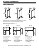
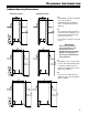
Planning Information Appliance Dimensions MRB 2400 MRB 3000 MRB 3600 Stated minimum height dimensions include when the levelled feet are fully inserted. Width will increase by 1/4" (6.5 mm) when mounting strips are installed. Door Swing Clearance MRB 2400 (top view) MRB 3000 MRB 3600 Inset installation style A = 10 3/4" (273 mm) B = 1/2" (12.5 mm) C = 25 7/8" (658 mm) Inset installation style A = 13 1/4" (337 mm) B = 1/2" (12.
Planning Information Cabinet Opening Dimensions Continous toe kick Individual toe kick A Cabinet depth frameless installation style = 24" (610 mm) Cabinet depth inset installation style = 24" (610 mm) plus panel thickness B This is the point where the power cord exits from the appliance rear. 3/4" (19 mm) from the left and 5" (127 mm) from the floor. Free length of the power cord is 98" (2.5 m).
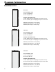
Planning Information Panel Dimensions 24" recess Inset installation style H = 79 7/8" (2029 mm) W = 23 3/4" (603 mm) Frameless installation style H = 80" (2032 mm) plus overlapping of the panel on the top W = 24" (610 mm) plus overlapping of the panel on both sides Minimum panel thickness = 5/8" (16 mm) Maximum panel thickness = 3/4" (19 mm) Maximum panel weight = 52 lbs (24 kg) 30" recess Inset installation style H = 79 7/8" (2029 mm) W = 29 3/4" (756 mm) Frameless installation style H = 80" (2032 mm) plu
Unpacking Unpacking 1. Cut the straps and remove them. 2. Press in the lug, tear the carton on the edge and remove it. 3. Remove all styrofoam packing material from the sides and top. 7. Remove the safety transportation brackets. Remove the packed cover strips and support strips from the appliance rear. 4. Remove the box with mounting parts. WARNING! Risk of injury and damage. Four people are required to safely remove the appliance from the bottom pallet. 5. Remove the ventilation grille. 8.
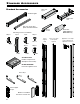
Standard Accessories Standard Accessories Door rack 2 pcs. Ventilation grille Gallon door rack Top cover for the door panel attachment bracket 10 mm wrench Retaining screws for installation 30 pcs. 8 pcs. 2 pcs. 20 pcs. M6 x 12 16 pcs. 20 pcs. SmartDeviceBox Includes component for Smartphone Connectivity DO NOT DISCARD! Forward to appliance user! TorxTM keys Panel support 10 pcs.
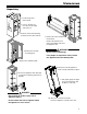
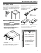
Blocking for Safety Anti-Tipping Device The anti-tipping device is mounted on the back wall in the recess at the finished installation height. After the appliance is in the recess and raised in height, the hook of the bracket will connect with the appliance top and prevent tipping. Adjustment of the anti-tipping bracket for use in a 25" deep recess Both base parts of the bracket must be adjusted for use in a recess with a depth of 25". - Loosen the screws. - Move the base part back or forth.
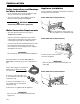
Installation Safety Instructions and Warnings for Water Connection • Do not install the water connection while the appliance is connected to an electrical outlet. • The connection to the water supply may only be made by a trained and licensed plumber. Appliance Installation Move the appliance towards the final position and leave enough space to work behind. Models MRB 3000 and MRB 3600 only WARNING! Connect to potable water supply only.
Installation Models MRB 3000 and MRB 3600 only Insert the water filter as far as it will go with the front knobs in a horizontal position and turn clockwise until it snaps in. Route the power cord towards the electrical outlet. Apply the appliance cover strips to the left and right front edge of the appliance housing, align in height with the top profile and screw into place. The strip is transparent so the designed mounting holes on the appliance housing are visible.
Installation Remove the transit supports using the Torx 25 key. Mount the ventilation grille with the grille segments tilted down. DANGER! Risk of death or serious injury due to appliance tipping. Do not open the appliance door before the height adjustment is finished and the antitipping bracket supports the appliance. Fasten the appliance in the recess through the appliance cover strips using eight screws 4 x 14 for each side. Left Turn clockwise to raise the appliance.
Installation Push the mounting strip upwards. The bottom edge of the mounting strip must be aligned with the top edge of the adjacent cabinet door. Position the attachment bracket in the middle of the door panel, align horizontally and secure to the door panel using eight 4 x 14 screws. Inset installation style Frameless installation style IMPORTANT Door handles should be mounted now because the side support strips will cover the mounting holes. Open the door.
Installation IMPORTANT Position the panel support strips with the top lug in the cut of the top attachment bracket. Align the strips parallel to the side edge of the panel and screw into place with ten 4 x 14 screws. If the door has to be limited to a 90° opening angle, it must be done before the panel is mounted onto the appliance door. See chapter “Important Note for Changing over Door Hinges or Limiting the Hinges to a 90° Opening Angle” on page 17. Open the appliance door.
Installation Align the panel in its vertical position if necessary. Align the panel in its depth at the bottom. Loosen the screws, align the panel and tighten the screws. Use the Torx 20 key provided. Loosen the hex nuts and turn the adusting bolts with the Torx 15 key provided. Align the panel horizontally with the long holes in the attachment bracket. Fasten the panel through the bottom attachment bracket with two screws 4 x 14. Tighten the hex nuts. Use the 10 mm wrench provided.
Installation Insert the panel supports into the support strips between panel and appliance door and screw into place with two screws M6 x 12 each. 16 Hook the door cover strips at the front of the supports and snap in at the back.
Installation Click cover into place. Important Note for Changing over Door Hinges or Limiting the Hinges to a 90° Opening Angle Changing the door hinges or limiting the hinges to a 90° opening angle should only be carried out by a trained expert. The door hinges are fitted with strong closing springs. If the hinge accidentally snaps shut, this can lead to serious injury. The door itself is very heavy. Do not try to dismount the door yourself. Contact the Liebherr service for more information.
For Service in the U.S. Liebherr Service Center Toll Free: 1-866-LIEBHER or 1-866-543-2437 Email: Service-appliances.us@liebherr.com PlusOne Solutions, Inc. 3501 Quadrangle Blvd, Suite 120 Orlando, FL 32817 For Service in Canada Liebherr Service Center Toll Free: 1-888-LIEBHER or 1-888-543-2437 www.euro-parts.ca EURO-PARTS CANADA 39822 Belgrave Road Belgrave, Ontario, N0G 1E0 Phone: (519) 357-3320 Fax: (519) 357-1326 w w w. l i e b h e r r - a p p l i a n c e s .