
Assembly and installation instructions


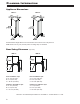
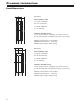


Appliance Dimensions
MW 24..MW 18..
Stated minimum height dimensions include when the levelled feet are fully inserted.
Width will increase by 1/4" (6.5 mm) when mounting strips are installed.
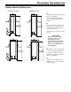
Door Swing Clearance (top view)
MW 24..
Dimension A and B: Add panel thickness and handle to calculate distance to wall.
Inset installation style
A = 10 3/4" (273 mm)
B = 1/2" (12.5 mm)
C = 25 7/8" (658 mm)
Frameless installation style
A = 11" (279 mm)
B = 1/2" (12.5 mm)
C = 26 3/8" (670 mm)
6
p
lannIng
I
nformatIon
Inset installation style
A = 8 1/4" (210 mm)
B = 1/2" (12.5 mm)
C = 19 7/8" (505 mm)
Frameless installation style
A = 8 1/2" (216 mm)
B = 1/2" (12.5 mm)
C = 20 3/8" (517 mm)
MW 18..