Installation instructions Under-worktop refrigerators and freezers, for integrated use 211111 7085270 - 00 UIK/ UIG ...
General safety information Contents 1 General safety information................................... 2 2 2.1 2.2 2.3 2.4 Putting into operation............................................ Installing the appliance............................................. Changing over door hinges...................................... Built-in...................................................................... Connecting the appliance.........................................
Putting into operation If the appliance is installed in a very damp environment, condensate may form on the outside of the appliance. u Always see to good ventilation at the installation site. 2.2.2 Demount door 2.2 Changing over door hinges NOTICE Risk of damage by condensate to appliances installed side-byside! If refrigerator and freezer are installed side-by-side, the freezer always has to be to the right of the refrigerator, as seen from the front. u Do not change over the door hinges.
Putting into operation u Transfer top and bottom fastening screws Fig. 2 (2) to the opposite side. Screws are self-tapping. Use cordless screwdriver: u Unscrew Fig. 5 (7) the hinges from the door, transfer them diagonally and screw them firmly into place (with 4 Nm). u Close the vacated fastening holes with the accompanying stoppers Fig. 5 (6). Fig. 5 2.2.5 Re-fit soft stop mechanism* Fig. 7 Fig. 6 u Screw the ball stud Fig. 6 (3) firmly into the new fastening hole (with 4 Nm) (Torx® 25).
Putting into operation Recess height A Height of unit plinth B Height of unit door C Base height of unit plinth D 820 mm 100 mm 716 mm 100 mm 820 mm 170 mm 646 mm 100 mm 870 mm 150 mm 716 mm 150 mm 870 mm 220 mm 646 mm 150 mm Note u Before assembling the door of the unit, make sure that the admissable weight of the unit door is not exceeded. u Otherwise damage to the hinges and resultant malfunction cannot be ruled out. Model Max. weight of unit door UIK 10 kg UIG 20 kg 2.3.
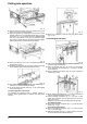
Putting into operation Fig. 12 u Pull the plinth forwards to remove it. Possibly remove the bottom door rack for easier installation. u Align the appliance by adjusting the feet so that it stands straight: Extend the rear adjustable-height feet by turning the screws Fig. 12 (3). Extend the front adjustable-height feet using a screwdriver, if they are fully retracted extend them using an 8-mm Allen key. Appliance should be slightly clamped in the recess, between floor and worktop! Fig.
Putting into operation Fig. 20 u u u u u w u Fig. 18 Attach the unit door to the adjusting bolts Fig. 18 (13) and loosely screw the locknuts Fig. 18 (10) onto them. Close the door. Check the gap between the door and the surrounding unit doors. To laterally align the door: push unit door in X direction. Align the door vertically Y and in the lateral inclination: adjust adjusting bolts Fig. 18 (13) with a screwdriver. The unit door is flush and in alignment with the surrounding unit fronts.
Putting into operation For appliances without soft stop mechanism adjust door stop cushioning. The door stop cushioning can be adjusted if necessary using the accompanying Allen key 5: u For stronger spring force: turn clockwise. u For lesser spring force (as-delivered): turn anticlockwise. Check the following points to ensure the appliance is fitted properly.